Chapter 15
15-4
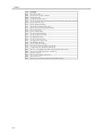
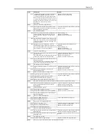
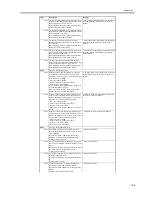
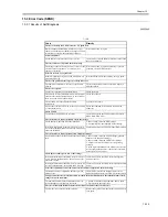
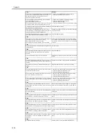
0000 The absence of the fixing web has been detected for
5 sec or more.
- Replace the fixing web.
- Replace the fixing web length sensor.
- Replace the DC controller PCB.
After correcting the fault, be user to reset the
fixing web counter reading.
(COPIER>COUNTER>MISC>FIX-WEB)
0001 At power-on, the connection of the web solenoid is
not detected.
- Check the connector for any fault in connection.
- Replace the solenoid.
0010 The power has been turned off and then back on
without resetting the error.
- Reset the fixing web counter.
(COPIER>COUNTER>MISC>FIX-WEB)
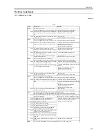
E010
There is a feed motor error.
0000 The FG signal of the feed motor does not arrive for
2 sec or more even when the feed motor has been
turned on.
- Check the connector for any fault in connection.
- Replace the motor
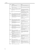
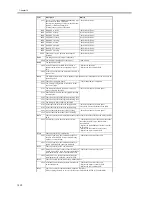
E012
There is a drum motor error.
0000 The FG signal of the drum motor does snot arrive
for 2 sec or more even when the drum motor has
been turned on.
- Check the connector for any fault in connection.
- Replace the motor.
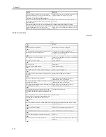
E013
The waste toner pipe is clogged.
0000 The waste toner pipe is identified as being clogged
for 4 sec or more.
- Check the connector for any fault in connection.
- Replace the waste toner feedscrew lock
detecting switch.
- Replace the waste toner feed unit.
- Replace the DC controller PCB.
E014
There is a fixing motor error.
0000 The PULL lock signal of the fixing motor does not
arrive for 2 sec even when the fixing motor has
been turned on.
- Check the connector for any fault in connection.
- Replace the motor.
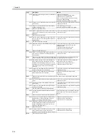
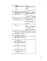
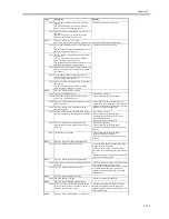
E020
There is no toner in the developing assembly; there is an error in the detection of developing toner
sensor connection; there is an error in the detection of hopper toner sensor connection
0000 The presence of toner is detected inside the sub
hopper and, in addition, the absence of toner is
detected inside developing assembly for 120 sec
continuously even when operation has been under
way for the supply of toner to the developing
assembly.
- Check the connector of the developing toner
sensor for any fault in connection.
- Replace the developing toner sensor.
- Replace the hopper toner sensor.
0001 At power-on, the connection of the developing
assembly toner sensor is not detected.
- Check the connector for any fault in connection.
- Replace the sensor.
0002 At power-on, the connection of the developing
hopper toner sensor is not detected.
- Replace the connector for any fault in
connection.
- Replace the sensor.
E025
There is a toner feed motor over-current detection error, there is a toner bottle motor connection
detection error.
0001 An over-current has been detected in the toner feed
motor.
- Check the connector for any fault in connection.
- Replace the motor.
0002 An over-current has been detected in the toner
bottle motor.
- Check the connector for any fault in connection.
- Replace the motor.
0003 At power-on, the connection of the toner bottle
motor is not detected.
- Check the connector for any fault in connection.
- Replace the motor.
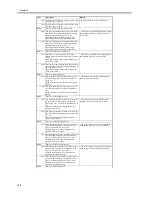
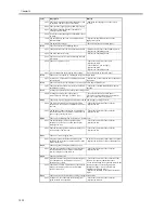
E032
The NE controller counter has malfunctioned.
0001 An open circuit has been detected for the count
pulse signal.
Turn off the main power, and check for an open
circuit in the cable; then, turn the main power
back on.
E061
There is a potential control error/there is an APC error.
0001 As a result of potential control, the drum surface
potential (VL2) of the background is 200 V or
higher (i.e., causing a solid black image).
- Replace the potential sensor unit.
- Replace the laser scanner unit.
- Replace the DC controller PCB.
0002 The primary charging output used at time of printer
output and the drum surface potential after laser
output is identified as being 200 V or more (i.e.,
causing a solid black image).
E100
There is a BD error.
0001 A check is made of VLOCK at intervals of 100
msec while the laser is on. An error will be
identified if it is not detected 10 times in sequence.
- Replace the laser scanner unit.
- Replace the DC controller PCB.
E110
There is a polygon motor error.
Code
Description
Remedy
Summary of Contents for iR5570 Series
Page 1: ...Mar 29 2005 Service Manual iR6570 5570 Series ...
Page 2: ......
Page 6: ......
Page 26: ...Contents ...
Page 27: ...Chapter 1 Introduction ...
Page 28: ......
Page 30: ......
Page 55: ...Chapter 2 Installation ...
Page 56: ......
Page 58: ...Contents 2 9 3 Mounting the Cassette Heater 2 34 ...
Page 98: ......
Page 99: ...Chapter 3 Basic Operation ...
Page 100: ......
Page 102: ......
Page 110: ......
Page 111: ...Chapter 4 Main Controller ...
Page 112: ......
Page 114: ......
Page 135: ...Chapter 5 Original Exposure System ...
Page 136: ......
Page 181: ...Chapter 6 Laser Exposure ...
Page 182: ......
Page 184: ......
Page 192: ......
Page 193: ...Chapter 7 Image Formation ...
Page 194: ......
Page 198: ......
Page 259: ...Chapter 8 Pickup Feeding System ...
Page 260: ......
Page 350: ......
Page 351: ...Chapter 9 Fixing System ...
Page 352: ......
Page 401: ...Chapter 10 External and Controls ...
Page 402: ......
Page 406: ......
Page 448: ......
Page 449: ...Chapter 11 MEAP ...
Page 450: ......
Page 452: ......
Page 455: ...Chapter 12 Maintenance and Inspection ...
Page 456: ......
Page 458: ......
Page 468: ......
Page 469: ...Chapter 13 Standards and Adjustments ...
Page 470: ......
Page 505: ...Chapter 14 Correcting Faulty Images ...
Page 506: ......
Page 508: ......
Page 537: ...Chapter 15 Self Diagnosis ...
Page 538: ......
Page 540: ......
Page 565: ...Chapter 16 Service Mode ...
Page 566: ......
Page 568: ......
Page 633: ...Chapter 17 Upgrading ...
Page 634: ......
Page 636: ......
Page 641: ...Chapter 17 17 5 F 17 4 HDD Boot ROM Flash ROM System Software ...
Page 646: ...Chapter 17 17 10 F 17 11 8 Click START F 17 12 ...
Page 675: ...Chapter 17 17 39 F 17 59 2 Select the data to download F 17 60 3 Click Start ...
Page 677: ...Chapter 18 Service Tools ...
Page 678: ......
Page 680: ......
Page 683: ...Mar 29 2005 ...
Page 684: ......

