Chapter 15
15-5
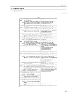
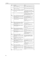
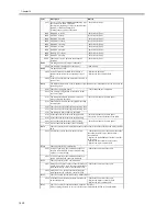
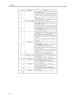
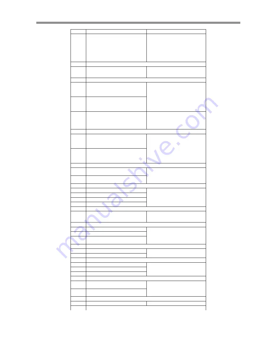
0001 - Although the polygon motor has been turned on,
VLOCK is not detected at all within 76.5 sec.
- At time of a shift from full-speed to half-speed
control, VLOCK is not detected at all for 7.5 sec.
- At time of half-speed control, a check is made of
VLOCK at intervals of 100 msec. An error will be
identified if it is not detected 10 times
continuously.
- Replace the laser scanner unit.
- Replace the DC controller PCB.
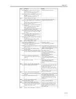
E121
There is a controller cooling fan error.
0001 Even though the controller cooling fan has been
turned on, the controller cooling fan stop signal has
been detected for 5 sec or more.
- Check the connector for any fault in connection.
- Replace the fan.
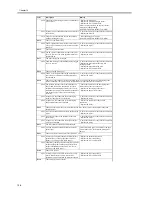
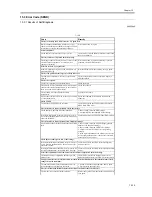
E196
The EEPROM is faulty.
1abb There is a mismatch between the data that has been
written in EEPROM and the data that has been
read. (a: chip No. 0 through 5; bb: chip faulty
address)
- Initialize the RAM.
- Replace the EEPROM.
- Replace the DC controller PCB.
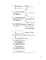
2abb The ID in EEPROM that has been read and the ID
in ROM are compared. An error will be identified
if they do not match. (a: chip No. 0 through 5; bb:
chip faulty address)
3abb When the main power is turned on, the ID in
EEPROM and the ID in ROM are compared. An
error will be identified if they do not match. (a: chip
No. 0 through 5; bb: chip faulty address)
- Check the position and condition of the
EEPROM.
- Initialize the RAM.
- Replace the EEPROM.
- Replace the DC controller PCB.
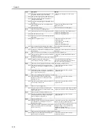
E202
There is a scanner HP error.
0001 An error has occurred when the sensor was moved
to home position.
The scanner HP sensor is faulty; the scanner motor
is faulty; the reader controller PCB is faulty.
- Check the connector for any fault in connection.
- Replace the scanner HP sensor.
- Replace the scanner motor.
- Replace the reader controller PCB.
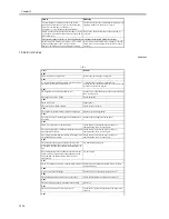
0002 An error has occurred when the sensor was moved
from home position.
The scanner HP sensor is faulty; the scanner motor
is faulty; the reader controller PCB is faulty.
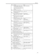
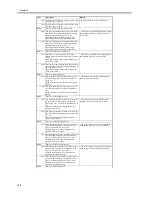
E225
The intensity of light is inadequate.
0001 At time of shading, the intensity if below a specific
level.
- Check the connector for any fault in connection.
- Replace the scanning lamp.
- Replace the inverter PCB.
- Replace the reader controller PCB.
0002 ADFThe intensity is below a specific level
between sheets (ADF).
E227
there is an error in the power supply (24 V).
0001 At power-on, the 24-V port is OFF.
- Check the connector for any fault in connection.
- Replace the power supply.
0002 At the start of a job, the 24-V port is OFF.
0003 At the end of a job, the 24-V port is off.
0004 When a load is driven, the 24-V port is OFF.
E240
The communication between the main controller PCB and the DC controller PCB is faulty.
0000 There is an error in the communication between the
main controller PCB and the CPU of the DC
controller PCB.
- Check the connector for any fault in connection.
- Replace the DC controller PCB.
- Replace the main controller PCB.
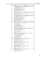
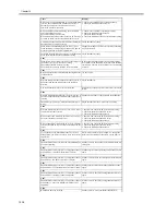
E248
There is an EEPROM error.
0001 An error has occurred at power-on.
- Replace the EEPROM.
- Replace the reader controller PCB.
0002 An error has occurred at time of write operation.
0003 An error has occurred at time of read operation
after write operation.
E315
There is a fault in the image data.
0007 There is a JIBIG encode error.
- Turn off and then back on the power.
000d There is a JBIG decode error.
E400
There is an ADF communication error.
0001 There is a check sum error.
- Check the connector for any fault in connection.
- Replace the reader controller PCB.
- Replace the ADF controller PCB.
0002 There is a reception status error.
0003 There is a reception interrupt error.
E413
There is a fault in the ADF shift motor.
0001 The output of the shift HP sensor is identified as
indicating open.
- Check the connector for any fault in connection.
- Replace the sensor and motor in question.
- Check the mounting condition of the area around
the cam.
0002 The output of the shift HP sensor is identified as
indicating closed.
E490
The ADF type is wrong.
0001 The ADF is not of a supported type.
- Replace the ADF with a supported type.
E503
There is an error in the finisher internal communication (finisher).
Code
Description
Remedy
Summary of Contents for iR5570 Series
Page 1: ...Mar 29 2005 Service Manual iR6570 5570 Series ...
Page 2: ......
Page 6: ......
Page 26: ...Contents ...
Page 27: ...Chapter 1 Introduction ...
Page 28: ......
Page 30: ......
Page 55: ...Chapter 2 Installation ...
Page 56: ......
Page 58: ...Contents 2 9 3 Mounting the Cassette Heater 2 34 ...
Page 98: ......
Page 99: ...Chapter 3 Basic Operation ...
Page 100: ......
Page 102: ......
Page 110: ......
Page 111: ...Chapter 4 Main Controller ...
Page 112: ......
Page 114: ......
Page 135: ...Chapter 5 Original Exposure System ...
Page 136: ......
Page 181: ...Chapter 6 Laser Exposure ...
Page 182: ......
Page 184: ......
Page 192: ......
Page 193: ...Chapter 7 Image Formation ...
Page 194: ......
Page 198: ......
Page 259: ...Chapter 8 Pickup Feeding System ...
Page 260: ......
Page 350: ......
Page 351: ...Chapter 9 Fixing System ...
Page 352: ......
Page 401: ...Chapter 10 External and Controls ...
Page 402: ......
Page 406: ......
Page 448: ......
Page 449: ...Chapter 11 MEAP ...
Page 450: ......
Page 452: ......
Page 455: ...Chapter 12 Maintenance and Inspection ...
Page 456: ......
Page 458: ......
Page 468: ......
Page 469: ...Chapter 13 Standards and Adjustments ...
Page 470: ......
Page 505: ...Chapter 14 Correcting Faulty Images ...
Page 506: ......
Page 508: ......
Page 537: ...Chapter 15 Self Diagnosis ...
Page 538: ......
Page 540: ......
Page 565: ...Chapter 16 Service Mode ...
Page 566: ......
Page 568: ......
Page 633: ...Chapter 17 Upgrading ...
Page 634: ......
Page 636: ......
Page 641: ...Chapter 17 17 5 F 17 4 HDD Boot ROM Flash ROM System Software ...
Page 646: ...Chapter 17 17 10 F 17 11 8 Click START F 17 12 ...
Page 675: ...Chapter 17 17 39 F 17 59 2 Select the data to download F 17 60 3 Click Start ...
Page 677: ...Chapter 18 Service Tools ...
Page 678: ......
Page 680: ......
Page 683: ...Mar 29 2005 ...
Page 684: ......


