Chapter 7
7-12
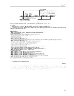
2. when the wire cleaning mechanism is executed in service mode:
COPIER>FUNCTION>CLEANING>WIRE-CLN*1
3. after the end of cleaning, at the end of every 2,000 prints*2
4. in a low temperature or high humidity environment, if the fixing roller is 160 deg C or less when the power is turned on
*1: The machine executes it when the primary charging wire or the transfer charging wire has been replaced.
*2: The default cleaning interval may be changed in service mode (COPIER> OPTION> BODY> W-CLN-P).
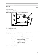
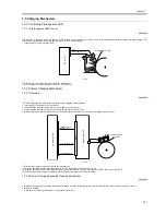
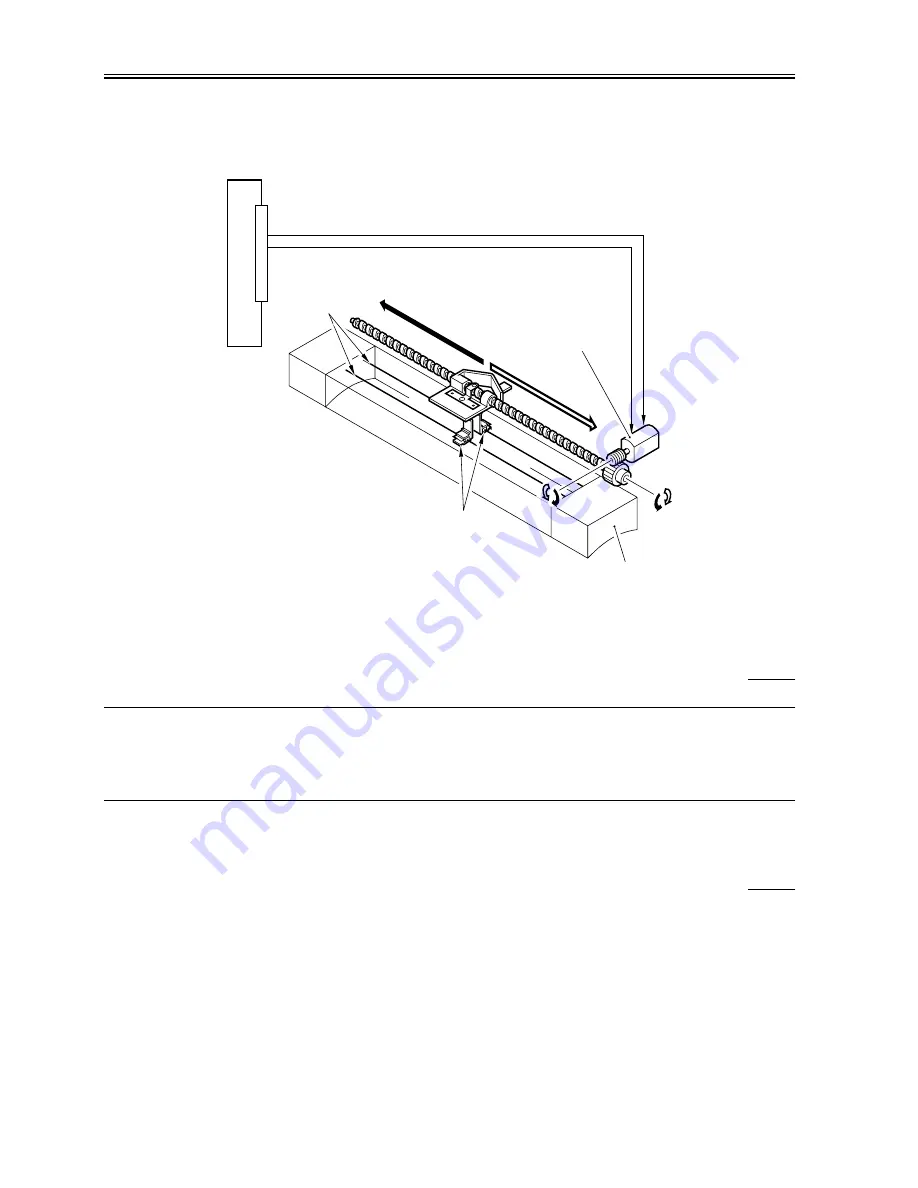
F-7-15
The following signals are associated with the mechanism:
[1] Primary charging wire cleaning motor reverse direction signal; when '1', the wire cleaner moves toward the rear.
[2] Primary changing wire cleaning motor normal direction signal; when '1', the wire cleaner moves toward the front.
7.5.2.3 Others
0009-4075
SERVICE MODE:
COPIER>FUNCTION>CLEANING>WIRE-CLN
Use it so that the machine causes the wire cleaner to make 5 round trips to automatically clean the charging wire when the primary charging wire or the
transfer wire has been replaced.
COPIER>OPTION>BODY>W-CLN-P
Use it to specify the interval at which the primary charging wire is automatically cleaned in terms of the number of prints made.
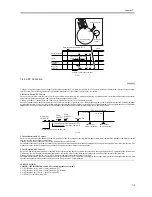
7.5.3 Dust-Collecting Roller Bias
7.5.3.1 Overview
0009-4077
The machine is equipped with a dust-colleting roller to collect stray toner occurring after development. The toner collected on its surface is removed by
the work of a scraper.
The following item is associated with the dust-collecting roller bias control system:
1. turning on/off the dust-collecting roller bias
The following shows the construction of the dust-collecting roller bias:
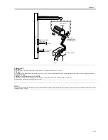
Primary changing assembly
Wire
DC controller PCB
(to rear)
(to front)
PRIMARY_CLEAN_OUT1 [1]
J103A
Wire cleaner
PRIMARY_CLEAN_OUT2 [2]
Primary charging
wire cleaning motor
(M6)
Summary of Contents for iR6570 series
Page 1: ...Mar 29 2005 Service Manual iR6570 5570 Series...
Page 2: ......
Page 6: ......
Page 26: ...Contents...
Page 27: ...Chapter 1 Introduction...
Page 28: ......
Page 30: ......
Page 55: ...Chapter 2 Installation...
Page 56: ......
Page 58: ...Contents 2 9 3 Mounting the Cassette Heater 2 34...
Page 98: ......
Page 99: ...Chapter 3 Basic Operation...
Page 100: ......
Page 102: ......
Page 110: ......
Page 111: ...Chapter 4 Main Controller...
Page 112: ......
Page 114: ......
Page 135: ...Chapter 5 Original Exposure System...
Page 136: ......
Page 181: ...Chapter 6 Laser Exposure...
Page 182: ......
Page 184: ......
Page 192: ......
Page 193: ...Chapter 7 Image Formation...
Page 194: ......
Page 198: ......
Page 259: ...Chapter 8 Pickup Feeding System...
Page 260: ......
Page 350: ......
Page 351: ...Chapter 9 Fixing System...
Page 352: ......
Page 401: ...Chapter 10 External and Controls...
Page 402: ......
Page 406: ......
Page 448: ......
Page 449: ...Chapter 11 MEAP...
Page 450: ......
Page 452: ......
Page 455: ...Chapter 12 Maintenance and Inspection...
Page 456: ......
Page 458: ......
Page 468: ......
Page 469: ...Chapter 13 Standards and Adjustments...
Page 470: ......
Page 505: ...Chapter 14 Correcting Faulty Images...
Page 506: ......
Page 508: ......
Page 537: ...Chapter 15 Self Diagnosis...
Page 538: ......
Page 540: ......
Page 565: ...Chapter 16 Service Mode...
Page 566: ......
Page 568: ......
Page 633: ...Chapter 17 Upgrading...
Page 634: ......
Page 636: ......
Page 641: ...Chapter 17 17 5 F 17 4 HDD Boot ROM Flash ROM System Software...
Page 646: ...Chapter 17 17 10 F 17 11 8 Click START F 17 12...
Page 675: ...Chapter 17 17 39 F 17 59 2 Select the data to download F 17 60 3 Click Start...
Page 677: ...Chapter 18 Service Tools...
Page 678: ......
Page 680: ......
Page 683: ...Mar 29 2005...
Page 684: ......

