Chapter 16
16-43
F-16-14
16.16.3 Scan Test
16.16.3.1 Scan Test ((2) SCAN TEST)
0017-7806
Scan test ((2) SCAN TEST)
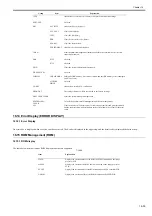
Press the numeric keypad key 2 on the test mode menu to select the CCD test.
Press numeric keypad keys 1 and 4 during the CCD test to carry out the individual tests described below.
Numeric keypad key 1
Corrects the LED output of the contact sensor and sets its parameters automatically. (AGC adjustment)
Numeric keypad key 4 (CIS shift type only)
Detects trash at reader scan positions A/B/C.
Pos A: Reference read position
Pos B: About 0.5 mm inside of the roller from the reference position
Pos C: About 1.0 mm inside of the roller from the reference position
16.16.4 Print Test
16.16.4.1 Print Test ((3) PRINT TEST)
0017-7807
Print test ((3) PRINT TEST)
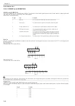
Press the numeric keypad key 3 on the test mode menu to select the print test.
Press numeric keypad keys 2 and 4 during the print test to generate test patterns as described below. Two kinds of service test patterns are available. Other test
patterns are reserved for factory/development purposes.
Numeric keypad key 2
(2) BLACK: All-black output
Numeric keypad key 4
(4) ENDURANCE: Black belt output
To cancel test printing, press the stop key.
F-16-15
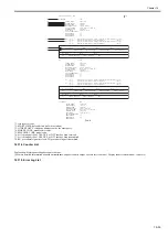
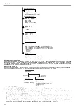
D-RAM
TEST
30208KB
D-RAM
TEST
30208KB
D-RAM
TEST
30208KB
complete
(error)
D-RAM
TEST
30208KB
[1] - [2]
D-RAM
TEST
30208KB
complete
(no error)
WRT= 33CC RD= 33EC
ADR= BF840201
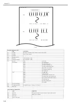
Use it to make sure that the print
pattern does not have white lines
or uneven image.
Use it to make sure that the print
pattern does not have contraction/
elongation of an image or dirt/black
line.s
Summary of Contents for Laser Class 810
Page 2: ......
Page 6: ......
Page 18: ...Contents...
Page 19: ...Chapter 1 Introduction...
Page 20: ......
Page 22: ......
Page 55: ...Chapter 1 1 33...
Page 56: ......
Page 57: ...Chapter 2 Installation...
Page 58: ......
Page 60: ......
Page 76: ......
Page 77: ...Chapter 3 Basic Operation...
Page 78: ......
Page 80: ......
Page 87: ...Chapter 3 3 7...
Page 88: ......
Page 89: ...Chapter 4 Original Exposure System...
Page 90: ......
Page 92: ......
Page 104: ......
Page 105: ...Chapter 5 Original Feeding System...
Page 106: ......
Page 108: ......
Page 126: ...Chapter 5 5 18...
Page 127: ...Chapter 6 Laser Exposure...
Page 128: ......
Page 130: ......
Page 134: ......
Page 135: ...Chapter 7 Image Formation...
Page 136: ......
Page 138: ......
Page 144: ......
Page 145: ...Chapter 8 Pickup and Feed System...
Page 146: ......
Page 148: ......
Page 161: ...Chapter 9 Fixing System...
Page 162: ......
Page 164: ......
Page 175: ...Chapter 10 External and Controls...
Page 176: ......
Page 180: ...Chapter 10 10 2 F 10 2 FM2000 FM1...
Page 197: ...Chapter 11 e Maintenance imageWARE Remote...
Page 198: ......
Page 200: ......
Page 210: ......
Page 211: ...Chapter 12 Maintenance and Inspection...
Page 212: ......
Page 214: ......
Page 216: ......
Page 217: ...Chapter 13 Measurement and Adjustments...
Page 218: ......
Page 220: ......
Page 226: ......
Page 227: ...Chapter 14 Correcting Faulty Images...
Page 228: ......
Page 230: ......
Page 236: ...Chapter 14 14 6 F 14 3 12 6 5 11 3 14 1 10 9 8 7 16 13 15 4 2...
Page 238: ...Chapter 14 14 8...
Page 239: ...Chapter 15 Error Code...
Page 240: ......
Page 242: ......
Page 249: ...Chapter 16 Service Mode...
Page 250: ......
Page 256: ...Chapter 16 16 2...
Page 304: ......
Page 305: ...Chapter 17 Upgrading...
Page 306: ......
Page 308: ......
Page 314: ......
Page 315: ...Chapter 18 Service Tools...
Page 316: ......
Page 317: ...Contents Contents 18 1 Service Tools 18 1 18 1 1 Special Tools 18 1...
Page 318: ......
Page 320: ......
Page 321: ...Mar 26 2010...
Page 322: ......


