1-5
Bef
ore Y
ou
Star
t
1
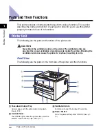
Parts and Their Functions
e
e
e
e
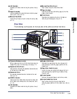
Lift Handles
Hold these handles when moving the printer. (See p.
5-26)
f
f
f
f
Paper Cassette
Can be loaded with up to 250 sheets of plain paper
(of 64 g/m
2
g
g
g
g
Manual Feed Slot
Used when printing a sheet at a time manually. (See
p. 2-10)
h
h
h
h
Manual Feed Slot Cover
Open when using the manual feed slot.
i
i
i
i
Paper Guides
Align them with the width of the paper so that the
paper is fed straight.
j
j
j
j
Front Cover
Opened when replacing the toner cartridge or
removing jammed paper. (See p. 5-3)
Rear View
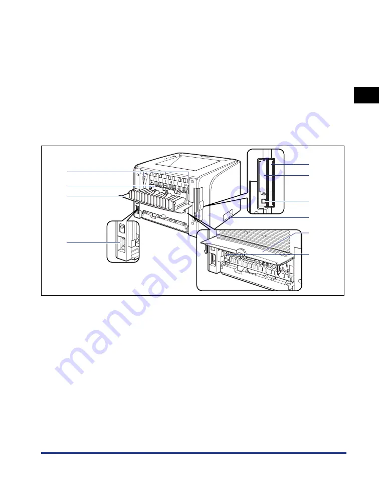
The following are the parts on the rear side of the printer and their functions.
a
a
a
a
Pressure Release Levers
When a paper jam occurs, tilt the lever toward you to
release the pressure in the fixing unit. (See p. 7-7)
b
b
b
b
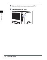
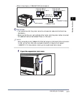
Expansion Slot Cover
Opened when installing the optional network board
or connecting a USB cable.
c
c
c
c
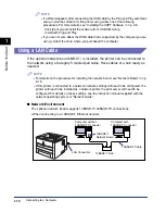
Expansion Slot
The optional network board is installed in this slot.
(See p. 6-19)
d
d
d
d
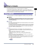
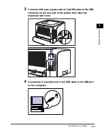
USB Connector
Connected to the USB cable. Connect the other end
of the cable to the USB port on the computer. (See
p. 1-13)
e
e
e
e
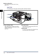
Lift Handles
Hold these handles when moving the printer. (See p.
5-26)
f
f
f
f
Duplex Unit Cover
Opened when specifying the size of paper for 2-
sided printing or removing paper jammed in the
duplex unit.
g
g
g
g
Paper Size Switch Lever
Switch the lever according to the paper size for 2-
sided printing when performing 2-sided printing.
(See p. 2-49)
h
h
h
h
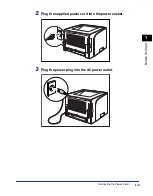
Power Socket
Connect the supplied power cord to this socket.
i
i
i
i
Output Selection Cover
Open when using the face-up output slot or
removing paper jammed in the output area. (See p.
2-17)
j
i
h
a
e
g
f
c
b
d
Summary of Contents for laser Shot LBP 3300
Page 2: ...LBP3300 Laser Printer User s Guide ...
Page 25: ...xxii ...
Page 45: ...1 20 Before You Start 1 Connecting to a Computer ...
Page 99: ...2 sided Printing 2 54 Loading and Outputting Paper 2 12 Click OK to start printing ...
Page 105: ...2 sided Printing 2 60 Loading and Outputting Paper 2 ...
Page 305: ...5 32 Routine Maintenance 5 Handling the Printer ...
Page 391: ...7 52 Troubleshooting 7 Confirming the Printer Features ...
Page 397: ...8 6 Appendix 8 Dimensions of Each Part Paper Feeder Unit PF 35 117 4 116 6 369 7 421 1 mm ...
Page 413: ...8 22 Appendix 8 Location of the Serial Number ...
Page 414: ...R IE 700AC CANON INC 2005 ...

