background image

Mar 31 2006

Service Manual

MF3220 Series

LaserBase MF3220

Summary of Contents for LaserBase MF3220 Series

Page 1: ...Mar 31 2006 Service Manual MF3220 Series LaserBase MF3220 ...

Page 2: ......

Page 3: ... need arises In the event of major changes in the contents of this manual over a long or short period Canon will issue a new edition of this manual The following paragraph does not apply to any countries where such provisions are inconsistent with local law Trademarks The product names and company names used in this manual are the registered trademarks of the individual companies Copyright This ma...

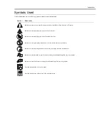
Page 4: ...quiring care to avoid combustion fire Indicates an item prohibiting disassembly to avoid electric shocks or problems Indicates an item requiring disconnection of the power plug from the electric outlet Indicates an item intended to provide notes assisting the understanding of the topic in question Indicates an item of reference assisting the understanding of the topic in question Provides a descri...

Page 5: ...sed to indicate Low The voltage value how ever differs from circuit to circuit In addition the asterisk as in DRMD indicates that the DRMD signal goes on when 0 In practically all cases the internal mechanisms of a microprocessor cannot be checked in the field Therefore the operations of the microprocessors used in the machines are not discussed they are explained in terms of from sensors to the i...

Page 6: ......

Page 7: ... 1 Overview Configuration 2 1 2 1 1 1 Overview 2 1 2 2 Laser Exposure 2 2 2 2 1 Overview Configuration 2 2 2 2 1 1 Overview 2 2 2 3 Image Formation 2 3 2 3 1 Overview Configuration 2 3 2 3 1 1 Overview 2 3 2 4 Pickup and Feed System 2 4 2 4 1 Overview Configuration 2 4 2 4 1 1 Overview 2 4 2 4 2 Other Control 2 4 2 4 2 1 Manual Pickup Control 2 4 2 4 2 2 Cassette Pickup Control 2 4 2 4 3 Detection...

Page 8: ...g the right cover 3 4 3 1 6 4 Removing the left cover 3 4 3 1 6 5 Removing the rear cover 3 4 3 1 6 6 Removing the Scanner Unit 3 5 3 1 6 7 Removing the Board Unit 3 5 3 1 6 8 Removing the Operation Panel Unit 3 5 3 1 7 SCNT Board 3 6 3 1 7 1 Removing the Cassette 3 6 3 1 7 2 Removing the front cover 3 6 3 1 7 3 Removing the right cover 3 6 3 1 7 4 Removing the left cover 3 6 3 1 7 5 Removing the ...

Page 9: ...canner Unit 3 15 3 1 12 8 Removing the Plate 3 15 3 1 12 9 Removing the Paper Delivery Sensor 3 15 3 2 Document Feed Exposure System 3 15 3 2 1 Scanner Unit 3 15 3 2 1 1 Removing the Cassette 3 15 3 2 1 2 Removing the front cover 3 15 3 2 1 3 Removing the right cover 3 16 3 2 1 4 Removong the left cover 3 16 3 2 1 5 Removing the rear cover 3 16 3 2 1 6 Removing the Scanner Unit 3 16 3 2 2 Scanner ...

Page 10: ...5 3 5 1 8 Removing the Right Frame 3 26 3 5 1 9 Removing the Plate 3 26 3 5 1 10 Removing the Left Frame 3 26 3 5 1 11 Removing the Power Supply Shield Plate 3 26 3 5 1 12 Removing the Power Supply Assembly 3 26 3 5 1 13 Removing the Gear Unit 3 27 3 5 1 14 Removing the Tooth Missing Gear 3 27 3 5 2 Cassette Pickup Solenoid 3 27 3 5 2 1 Removing the Cassette 3 27 3 5 2 2 Removing the front cover 3...

Page 11: ...te 3 36 3 5 6 2 Removing the front cover 3 36 3 5 6 3 Removing the right cover 3 36 3 5 6 4 Removing the left cover 3 37 3 5 6 5 Removing the rear cover 3 37 3 5 6 6 Removing the Scanner Unit 3 37 3 5 6 7 Removing the top cover 3 37 3 5 6 8 Removing the Right Frame 3 38 3 5 6 9 Removing the Plate 3 38 3 5 6 10 Removing the Left Frame 3 38 3 5 6 11 Removing the Power Supply Shield Plate 3 38 3 5 6 ...

Page 12: ... 4 3 4 Cleaning Method printer unit 4 2 4 4 Lubrications 4 3 4 4 1 Areas Requiring Application of Grease 4 3 4 4 2 Delivery Idler Gear 4 3 4 4 3 Wheel Shaft 4 4 4 4 4 Fixing Drive Transmission Gear 4 4 4 4 5 Large Gear 4 4 4 4 6 Feed Gear 4 5 4 4 7 Internal Gear 4 5 4 4 8 Large Gear Deceleration Gear Plate R 4 5 4 4 9 Large Gear Bushing R 4 6 4 4 10 Main Motor 4 6 4 4 11 Drive Releasing Arm 4 7 4 ...

Page 13: ...SSSW SW10 5 5 5 4 2 4 SSSW SW16 5 5 5 4 2 5 SSSW SW30 5 6 5 4 2 6 SSSW SW33 5 6 5 4 2 7 SSSW SW37 5 6 5 4 2 8 SSSW SW51 5 7 5 4 2 9 SSSW SW54 5 7 5 4 3 Report Output REPORT 5 7 5 4 3 1 SERVICE DATA LIST 5 7 5 4 4 Test Mode TEST 5 7 5 4 4 1 Faculty Test 5 7 Chapter 6 APPENDIX 6 1 Outline of Electrical Components 6 1 6 1 1 Sensor 6 1 6 1 1 1 Arrangement of Sensors and Switches 6 1 6 1 2 PCBs 6 2 6 1...

Page 14: ...Contents ...

Page 15: ...Chapter 1 PRODUCT DESCRIPTION ...

Page 16: ......

Page 17: ... Stack Upon Delivery 1 2 1 2 3 System Requirements for Printer Driver 1 2 1 3 Names of Parts 1 2 1 3 1 External View 1 2 1 3 2 Operation panel 1 3 1 4 Safety 1 4 1 4 1 Safety of Laser Light 1 4 1 4 2 Regulations Under the Center for Devices and Radiological Health CDRH 1 4 1 4 3 Handling the Laser Unit 1 4 1 4 4 Safety of Toner 1 4 1 4 5 Backup Battery 1 5 ...

Page 18: ......

Page 19: ...ec Cassette paper size A4 B5 A5 Letter Legal Executive Envelope DL ISO C5 COM10 MONARCH Multi purpose paper size A4 B5 A5 Letter Legal Executive Envelope DL ISO C5 COM10 MONARCH Cassette paper type Plain paper 64 to 90g m2 Heavy paper 105 to 128g m2 Recycled paper 64 to 80g m2 Transparencyp Envelope Multi purpose paper type Plain paper 64 to 90g m2 Heavy paper 105 to 128g m2 Recycled paper 64 to 8...

Page 20: ...down Face up Plain paper 64 to 90 g m2 Approx 60 sheets 1 sheet Heavy paper 105 to 128 g m2 Approx 30 sheets 1 sheet Transparency Approx 10 sheets 1 sheet Label Approx 10 sheets 1 sheet Envelope Approx 10 sheets 1 sheet OS CPU RAM Available Free Disk Space Windows 98 Intel Pentium 90 MHz or greater 32 MB of RAM 64 MB or greater is recommended At least 115 MB 200MB or greater is recommended Windows...

Page 21: ... Front cover 2 Platen glass 6 Multi purpose feeder 3 Operation panel 7 Cassette 4 Output tray 1 USB port 2 Face up cover 3 Power socket 4 Extension cover 1 Practice Memory 11 Collate 2on1 key 2 COPY Key 12 image Quality key 1 2 3 4 5 6 7 1 2 3 4 1 2 3 4 5 6 7 8 9 0 OK 1 19 18 17 16 15 14 13 12 11 10 2 3 4 5 6 7 8 9 ...

Page 22: ...en certified under the regulations and all laser products sold in the US must bear the label F 1 4 1 4 3 Handling the Laser Unit 0012 0866 The laser scanner unit emits invisible laser light inside it If exposed to laser light the human eye can irreparably be damaged Never attempt to disassemble the laser scanner unit It is not designed for servicing in the field The covers around the laser scanner...

Page 23: ...f the clothes 3 Do not bring toner into contact with vinyl material They are likely to react with each other 1 4 5 Backup Battery 0012 3263 The machine s SCNT PCB are equipped with a lithium battery 1 pc each serving as a backup source of power in the event of a power shortage or when the power plug is removed LISK OF EXPLOSION IF BATTERY IS REPLACED BY AN INCORRECT TYPE DISPOSE OF USED BATTERIES ...

Page 24: ......

Page 25: ...Chapter 2 TECHNICAL REFERENCE ...

Page 26: ......

Page 27: ...on Jams 2 5 2 4 3 1 Jam Detection Outline 2 5 2 4 3 1 1 Type so Jams 2 5 2 4 3 2 Delay Jams 2 5 2 4 3 2 1 Pickup Delay Jam 2 5 2 4 3 2 2 Delivery Delay Jam 2 5 2 4 3 3 Stationary Jams 2 5 2 4 3 3 1 Pickup Stationary Jam 2 5 2 4 3 3 2 Delivery Stationary Jam 2 5 2 4 3 4 Other Jams 2 5 2 4 3 4 1 Wrap Jam 2 5 2 4 3 4 2 Initial Jam 2 5 2 4 3 4 3 Cover Open Jam 2 5 2 5 Fixing Unit 2 6 2 5 1 Overview Co...

Page 28: ......

Page 29: ...ment Feed and Exposure System 2 1 1 Overview Configuration 2 1 1 1 Overview 0012 0870 F 2 1 T 2 1 The CIS unit driven by the flatbed motor reads out image data of a document on the platen glass 1 CIS unit 2 Flatbed motor 2 1 ...

Page 30: ...nal within 0 1 sec after the scanner motor is forced to accelerate It also detects a BD fault if it does not detect a specific interval of BDI signals for 2 sec continuously after the scanner motor has reached a specific revolution number of rotations Scanner Fault If the machine does not detect the BDI signal 1 4 sc after it has stopped forcing the scanner motor to accelerate it extends the perio...

Page 31: ...esulting toner image is then transferred to paper by the work of the transfer charging roller and the paper is sent to the fixing assembly The surface of the photo sensitive drum is cleaned by the cleaning blade so that it is free of residual toner after cleaning the primary charging roller once again charges the surface to an even negative potential to prepare for the formation of a new static la...

Page 32: ... become ready for operation the machine turns off the manual feed pickup solenoid to rotate the feed roller thus moving the paper forward the operation thereafter is identical to the operation used for pickup from the cassette 2 4 2 Other Control 2 4 2 1 Manual Pickup Control 0012 1874 Upon detection of manually inserted paper the machine drives the main motor for the specified time to feed the pa...

Page 33: ...ted the leading edge of paper 2 4 3 3 Stationary Jams 2 4 3 3 1 Pickup Stationary Jam 0012 0909 The machine identifies a pickup stationary jam if the top sensor does not detect the absence of paper within 3 575 sec after the top sensor has detected the leading edge of paper 2 4 3 3 2 Delivery Stationary Jam 0012 0911 The machine moves to a delivery stationary jam sequence if it does not detect a w...

Page 34: ...hoto triac couple thus cutting off the power to the fixing heater 2 Protective Mechanism by the Fixing Heater Safety Circuit The fixing heater safety circuit monitors the voltage of the fixing heater temperature detection signal from the main thermistor and the sub thermistor at all times If the fixing temperature appreciably exceeds a specific level the machine cuts off the power to the fixing he...

Page 35: ... while fixing heater temperature control is under way e the temperature of the main thermistor does not exceed 100 deg C within 20 sec after the start of start up temperature control f the CPU detects that the reading of the sub thermistor remains less than 35 deg C for 0 15 sec continuously while fixing heater temperature control is under way g the CPU detects that the reading of the sub thermist...

Page 36: ......

Page 37: ...Chapter 3 DISASSEMBLY AND ASSEMBLY ...

Page 38: ......

Page 39: ...over 3 3 3 1 6 Operation Panel Unit 3 4 3 1 6 1 Removung the Cassette 3 4 3 1 6 2 Removing the front cover 3 4 3 1 6 3 Removing the right cover 3 4 3 1 6 4 Removing the left cover 3 4 3 1 6 5 Removing the rear cover 3 4 3 1 6 6 Removing the Scanner Unit 3 5 3 1 6 7 Removing the Board Unit 3 5 3 1 6 8 Removing the Operation Panel Unit 3 5 3 1 7 SCNT Board 3 6 3 1 7 1 Removing the Cassette 3 6 3 1 7...

Page 40: ... 3 14 3 1 12 2 Removing the front cover 3 14 3 1 12 3 Removing the right cover 3 14 3 1 12 4 Removing the left cover 3 14 3 1 12 5 Removing the rear cover 3 14 3 1 12 6 Removing the Power Supply Shield Plate 3 14 3 1 12 7 Removing the Scanner Unit 3 15 3 1 12 8 Removing the Plate 3 15 3 1 12 9 Removing the Paper Delivery Sensor 3 15 3 2 Document Feed Exposure System 3 15 3 2 1 Scanner Unit 3 15 3 ...

Page 41: ...24 3 5 1 2 Removing the front cover 3 24 3 5 1 3 Removing the right cover 3 25 3 5 1 4 Removing the left cover 3 25 3 5 1 5 Removing the rear cover 3 25 3 5 1 6 Removing the Scanner Unit 3 25 3 5 1 7 Removing the top cover 3 25 3 5 1 8 Removing the Right Frame 3 26 3 5 1 9 Removing the Plate 3 26 3 5 1 10 Removing the Left Frame 3 26 3 5 1 11 Removing the Power Supply Shield Plate 3 26 3 5 1 12 Re...

Page 42: ...10 Removing the Left Frame 3 35 3 5 5 11 Removing the Power Supply Shield Plate 3 35 3 5 5 12 Removing the Power Supply Assembly 3 36 3 5 5 13 Removing the Manual Pickup Solenoid 3 36 3 5 6 Main Motor 3 36 3 5 6 1 Removing the Cassette 3 36 3 5 6 2 Removing the front cover 3 36 3 5 6 3 Removing the right cover 3 36 3 5 6 4 Removing the left cover 3 37 3 5 6 5 Removing the rear cover 3 37 3 5 6 6 R...

Page 43: ... 3 42 3 6 2 3 Removing the right cover 3 42 3 6 2 4 Removing the left cover 3 43 3 6 2 5 Removing the rear cover 3 43 3 6 2 6 Removing the Scanner Unit 3 43 3 6 2 7 Removing the top cover 3 43 3 6 2 8 Removing the Right Frame 3 44 3 6 2 9 Removing the Plate 3 44 3 6 2 10 Removing the Left Frame 3 44 3 6 2 11 Removing the Power Supply Shield Plate 3 44 3 6 2 12 Removing the Fixing Film Unit 3 44 3 ...

Page 44: ......

Page 45: ... cover 0012 1406 1 Open the front cover 1 and remove the arm claws 2 to disengage the connection 2 Remove the shafts on both sides 3 while warping the shaft arms inside and remove the front cover F 3 2 3 1 2 3 Removing the right cover 0012 1398 1 Remove the 2 screws 1 on the right cover F 3 3 2 Remove the right cover 1 2 screws 2 F 3 4 3 1 2 4 Removing the left cover 0012 1401 1 Remove the 2 screw...

Page 46: ...ght cover F 3 9 2 Remove the right cover 1 2 screws 2 F 3 10 3 1 3 4 Removing the left cover 0012 4420 1 Remove the 2 screws 1 on the left cover F 3 11 2 Remove the left cover 1 2 screws 2 F 3 12 3 1 3 5 Removing the rear cover 0012 4421 1 Opening the face up cover 1 and then lower the fixing pressure release levers 2 on both sides and release the pressure 2 Remove the rear cover 3 by sliding it t...

Page 47: ...e 3 1 4 2 Removing the front cover 0012 1436 1 Open the front cover 1 and remove the arm claws 2 to disengage the connection 2 Remove the shafts on both sides 3 while warping the shaft arms inside and remove the front cover F 3 17 3 1 4 3 Removing the right cover 0012 1437 1 Remove the 2 screws 1 on the right cover F 3 18 2 Remove the right cover 1 2 screws 2 F 3 19 3 1 5 Left Cover 3 1 5 1 Removi...

Page 48: ...arms inside and remove the front cover F 3 22 3 1 6 3 Removing the right cover 0012 1488 1 Remove the 2 screws 1 on the right cover F 3 23 2 Remove the right cover 1 2 screws 2 F 3 24 3 1 6 4 Removing the left cover 0012 1490 1 Remove the 2 screws 1 on the left cover F 3 25 2 Remove the left cover 1 2 screws 2 F 3 26 3 1 6 5 Removing the rear cover 0012 1491 1 Opening the face up cover 1 and then ...

Page 49: ...t to the rear and lifting it up 2 screws 2 F 3 29 3 1 6 7 Removing the Board Unit 0012 1494 1 Remove the four screw 1 onthe back of scanner unit F 3 30 2 Open the board unit 1 and disconnect the connector 2 and two flat cables 3 F 3 31 3 1 6 8 Removing the Operation Panel Unit 0012 1496 1 Detach the flat cable cover and remove the flat cable 1 from the core 2 2 screws 3 F 3 32 2 Remove the 2 claws...

Page 50: ...e right cover F 3 35 2 Remove the right cover 1 2 screws 2 F 3 36 3 1 7 4 Removing the left cover 0012 1500 1 Remove the 2 screws 1 on the left cover F 3 37 2 Remove the left cover 1 2 screws 2 F 3 38 3 1 7 5 Removing the rear cover 0012 1501 1 Opening the face up cover 1 and then lower the fixing pressure release levers 2 on both sides and release the pressure 2 Remove the rear cover 3 by sliding...

Page 51: ... 8 2 Removing the front cover 0012 1507 1 Open the front cover 1 and remove the arm claws 2 to disengage the connection 2 Remove the shafts on both sides 3 while warping the shaft arms inside and remove the front cover F 3 43 3 1 8 3 Removing the left cover 0012 1508 1 Remove the 2 screws 1 on the left cover F 3 44 2 Remove the left cover 1 2 screws 2 F 3 45 3 1 8 4 Removing the ECNT Board 0012 15...

Page 52: ...move the 2 screws 1 on the right cover F 3 48 2 Remove the right cover 1 2 screws 2 F 3 49 3 1 9 4 Removing the left cover 0012 1513 1 Remove the 2 screws 1 on the left cover F 3 50 2 Remove the left cover 1 2 screws 2 F 3 51 3 1 9 5 Removing the rear cover 0012 1514 1 Opening the face up cover 1 and then lower the fixing pressure release levers 2 on both sides and release the pressure 2 Remove th...

Page 53: ...mbly 2 Then pull it to remove the power supply assembly F 3 56 3 1 9 8 Removing the Power Supply Board 0012 1517 1 Remove the connector 1 and the flat cable 2 2 Remove the power supply board 3 3 spacers 4 4 screws 5 F 3 57 3 1 10 High voitage Power Supply PCB 3 1 10 1 Removing the Cassette 0012 1518 1 Remove the cassette by holding the cassette handle 3 1 10 2 Removing the front cover 0012 1519 1 ...

Page 54: ...ver 3 by sliding it to the rear 4 screws 4 F 3 63 3 1 10 6 Removing the Power Supply Shield Plate 0012 1524 1 Remove the cable from the cable guide 1 connector 1 F 3 64 2 Remove the power supply shield plate 1 9 screws 2 F 3 65 3 1 10 7 Removing the Power Supply Board 0012 1525 1 Remove the 3 screws 1 The external cover is omitted from the illustration below to show the instructions clearly 2 Remo...

Page 55: ... Remove the cassette by holding the cassette handle 3 1 11 2 Removing the front cover 0012 1528 1 Open the front cover 1 and remove the arm claws 2 to disengage the connection 2 Remove the shafts on both sides 3 while warping the shaft arms inside and remove the front cover F 3 69 3 1 11 3 Removing the right cover 0012 1531 1 Remove the 2 screws 1 on the right cover F 3 70 2 Remove the right cover...

Page 56: ... and remove the screw 3 Remove the flat cable from the core 2 Remove the 2 screws 4 and the 2 pins 5 on the right and left sides F 3 75 3 Remove the scanner unit 1 by sliding it to the rear and lifting it up 2 screws 2 F 3 76 3 1 11 7 Removing the top cover 0012 1538 1 Free the 2 claws 1 and remove the top cover 2 2 screws 3 F 3 77 3 1 11 8 Removing the Right Frame 0012 1539 1 Remove the right fra...

Page 57: ... omitted from the illustration below to show the instructions clearly 2 Remove the four connectors 2 as well as the flat cable 3 on the ECNT board After having removed the flat cable 3 store it inside the unit to protect it from damage F 3 83 3 As you remove the bosses on both sides 1 lower the front part of the power supply assembly 2 Then pull it to remove the power supply assembly F 3 84 3 1 11...

Page 58: ...550 1 Remove the 2 screws 1 on the right cover F 3 87 2 Remove the right cover 1 2 screws 2 F 3 88 3 1 12 4 Removing the left cover 0012 1551 1 Remove the 2 screws 1 on the left cover F 3 89 2 Remove the left cover 1 2 screws 2 F 3 90 3 1 12 5 Removing the rear cover 0012 1552 1 Opening the face up cover 1 and then lower the fixing pressure release levers 2 on both sides and release the pressure 2...

Page 59: ... ECNT board 3 screws 3 F 3 96 3 1 12 9 Removing the Paper Delivery Sensor 0012 1557 1 Remove the connector 1 on the ECNT board and detach the cable from the cable guide For better visibility the covers have been removed in the illustration 2 Remove the paper delivery sensor 2 1 screw 3 F 3 97 3 2 Document Feed Exposure System 3 2 1 Scanner Unit 3 2 1 1 Removing the Cassette 0012 1560 1 Remove the ...

Page 60: ...g the face up cover 1 and then lower the fixing pressure release levers 2 on both sides and release the pressure 2 Remove the rear cover 3 by sliding it to the rear 4 screws 4 F 3 103 3 2 1 6 Removing the Scanner Unit 0012 1567 1 Remove the connector 1 and the flat cable 2 on the ECNT board and remove the screw 3 Remove the flat cable from the core 2 Remove the 2 screws 4 and the 2 pins 5 on the r...

Page 61: ... the right cover F 3 107 2 Remove the right cover 1 2 screws 2 F 3 108 3 2 2 4 Removing the left cover 0012 1573 1 Remove the 2 screws 1 on the left cover F 3 109 2 Remove the left cover 1 2 screws 2 F 3 110 3 2 2 5 Removing the rear cover 0012 1574 1 Opening the face up cover 1 and then lower the fixing pressure release levers 2 on both sides and release the pressure 2 Remove the rear cover 3 by ...

Page 62: ...er cover unit 0012 1579 1 Remove the platen glass cover 2 Remove the scanner cover unit 1 4 front claws 2 3 claws each on the right and left sides 3 3 screws 4 F 3 116 3 2 3 Contact Sensor 3 2 3 1 Removing the Cassette 0012 1615 1 Remove the cassette by holding the cassette handle 3 2 3 2 Removing the front cover 0012 1616 1 Open the front cover 1 and remove the arm claws 2 to disengage the connec...

Page 63: ...move the rear cover 3 by sliding it to the rear 4 screws 4 F 3 122 3 2 3 6 Removing the Scanner Unit 0012 1620 1 Remove the connector 1 and the flat cable 2 on the ECNT board and remove the screw 3 Remove the flat cable from the core 2 Remove the 2 screws 4 and the 2 pins 5 on the right and left sides F 3 123 3 Remove the scanner unit 1 by sliding it to the rear and lifting it up 2 screws 2 F 3 12...

Page 64: ...1 1 connector 2 remove from the rear 2 screws 3 F 3 128 3 2 3 10 Removing the Contact Sensor 0012 1629 1 Remove the flat cable 1 and detach the contact sensor 3 while pushing the belt tension drive 2 in arrow direction F 3 129 3 2 4 Flatbed Motor Unit 3 2 4 1 Removing the Cassette 0012 1585 1 Remove the cassette by holding the cassette handle 3 2 4 2 Removing the front cover 0012 1586 1 Open the f...

Page 65: ...ng the face up cover 1 and then lower the fixing pressure release levers 2 on both sides and release the pressure 2 Remove the rear cover 3 by sliding it to the rear 4 screws 4 F 3 135 3 2 4 6 Removing the Scanner Unit 0012 1590 1 Remove the connector 1 and the flat cable 2 on the ECNT board and remove the screw 3 Remove the flat cable from the core 2 Remove the 2 screws 4 and the 2 pins 5 on the ...

Page 66: ... 3 claws each on the right and left sides 3 3 screws 4 F 3 140 3 2 4 9 Removing the Flatbed Motor Unit 0012 1600 1 Remove the flat bed motor unit 1 1 connector 2 remove from the rear 2 screws 3 F 3 141 3 3 LASER EXPOSURE SYSTEM 3 3 1 Laser Scanner Unit 3 3 1 1 Removing the Cassette 0012 1603 1 Remove the cassette by holding the cassette handle 3 3 1 2 Removing the front cover 0012 1605 1 Open the ...

Page 67: ...ng the face up cover 1 and then lower the fixing pressure release levers 2 on both sides and release the pressure 2 Remove the rear cover 3 by sliding it to the rear 4 screws 4 F 3 147 3 3 1 6 Removing the Scanner Unit 0012 1609 1 Remove the connector 1 and the flat cable 2 on the ECNT board and remove the screw 3 Remove the flat cable from the core 2 Remove the 2 screws 4 and the 2 pins 5 on the ...

Page 68: ...sfer Charging Roller 3 4 1 1 Removing the Transfer Charging Roller 0012 1633 1 Open the front cover 2 Hold the 2 claws 1 on the right side of the roller lifting them up 3 Slide the transfer charging roller 2 by sliding it to the right F 3 152 3 5 PICKUP AND FEEDING SYSTEM 3 5 1 Cassette Pickup Roller 3 5 1 1 Removing the Cassette 0012 1635 1 Remove the cassette by holding the cassette handle 3 5 1...

Page 69: ...e release levers 2 on both sides and release the pressure 2 Remove the rear cover 3 by sliding it to the rear 4 screws 4 F 3 158 3 5 1 6 Removing the Scanner Unit 0012 1640 1 Remove the connector 1 and the flat cable 2 on the ECNT board and remove the screw 3 Remove the flat cable from the core 2 Remove the 2 screws 4 and the 2 pins 5 on the right and left sides F 3 159 3 Remove the scanner unit 1...

Page 70: ... 1 11 Removing the Power Supply Shield Plate 0012 1646 1 Remove the cable from the cable guide 1 connector 1 F 3 165 2 Remove the power supply shield plate 1 9 screws 2 F 3 166 3 5 1 12 Removing the Power Supply Assembly 0012 1647 1 Remove the 3 screws 1 The external cover is omitted from the illustration below to show the instructions clearly 2 Remove the four connectors 2 as well as the flat cab...

Page 71: ...t 1 2 screws 2 F 3 171 2 Remove the spring 1 3 While freeing the claw detach the tooth missing gear 2 F 3 172 3 5 2 Cassette Pickup Solenoid 3 5 2 1 Removing the Cassette 0012 1656 1 Remove the cassette by holding the cassette handle 3 5 2 2 Removing the front cover 0012 1657 1 Open the front cover 1 and remove the arm claws 2 to disengage the connection 2 Remove the shafts on both sides 3 while w...

Page 72: ...he rear cover 3 by sliding it to the rear 4 screws 4 F 3 178 3 5 2 6 Removing the Scanner Unit 0012 1662 1 Remove the connector 1 and the flat cable 2 on the ECNT board and remove the screw 3 Remove the flat cable from the core 2 Remove the 2 screws 4 and the 2 pins 5 on the right and left sides F 3 179 3 Remove the scanner unit 1 by sliding it to the rear and lifting it up 2 screws 2 F 3 180 3 5 ...

Page 73: ...e cable guide 1 connector 1 F 3 185 2 Remove the power supply shield plate 1 9 screws 2 F 3 186 3 5 2 12 Removing the Power Supply Assembly 0012 1670 1 Remove the 3 screws 1 The external cover is omitted from the illustration below to show the instructions clearly 2 Remove the four connectors 2 as well as the flat cable 3 on the ECNT board After having removed the flat cable 3 store it inside the ...

Page 74: ...ile watching the lifting plate spring 2 carefully F 3 190 2 Remove the 2 claws 1 on both sides of the cassette separation pad and lift it up while watching the lifting plate spring 2 carefully Ensure that the separation pad spring does not get lost 3 Remove both the plate and the cassette separation pad 3 by sliding them to the left F 3 191 4 Remove the cassette separation pad 1 by sliding it upwa...

Page 75: ...r 4 screws 4 F 3 198 3 5 4 6 Removing the Scanner Unit 0012 1683 1 Remove the connector 1 and the flat cable 2 on the ECNT board and remove the screw 3 Remove the flat cable from the core 2 Remove the 2 screws 4 and the 2 pins 5 on the right and left sides F 3 199 3 Remove the scanner unit 1 by sliding it to the rear and lifting it up 2 screws 2 F 3 200 3 5 4 7 Removing the top cover 0012 1684 1 F...

Page 76: ... 2 Remove the power supply shield plate 1 9 screws 2 F 3 206 3 5 4 12 Removing the Power Supply Assembly 0012 1691 1 Remove the 3 screws 1 The external cover is omitted from the illustration below to show the instructions clearly 2 Remove the four connectors 2 as well as the flat cable 3 on the ECNT board After having removed the flat cable 3 store it inside the unit to protect it from damage F 3 ...

Page 77: ...ng the claw detach the tooth missing gear 2 F 3 212 3 5 4 15 Removing the Manual Stay 0012 1695 1 Release the lower claw 2 of the solenoid cover 1 and remove the solenoid cover 2 Remove the 3 screws 3 While watching the sensor flag carefully re move the manual stay 4 F 3 213 3 5 4 16 Removing the Paper Feed Guide 0012 1698 1 Remove the feed guide 1 1 screw 2 F 3 214 3 5 4 17 Removing the Paper Fee...

Page 78: ...he right cover 1 2 screws 2 F 3 218 3 5 5 4 Removing the left cover 0012 1704 1 Remove the 2 screws 1 on the left cover F 3 219 2 Remove the left cover 1 2 screws 2 F 3 220 3 5 5 5 Removing the rear cover 0012 1705 1 Opening the face up cover 1 and then lower the fixing pressure release levers 2 on both sides and release the pressure 2 Remove the rear cover 3 by sliding it to the rear 4 screws 4 F...

Page 79: ...t Frame 0012 1708 1 Remove the right frame 1 3 screws 2 F 3 225 3 5 5 9 Removing the Plate 0012 1709 1 Remove the plate 1 1 connector 2 on the ECNT board 3 screws 3 F 3 226 3 5 5 10 Removing the Left Frame 0012 1710 1 Remove the left frame 1 Remove the cable 2 from the guide 3 screws 3 F 3 227 3 5 5 11 Removing the Power Supply Shield Plate 0012 1711 1 Remove the cable from the cable guide 1 conne...

Page 80: ...o remove the power supply assembly F 3 231 3 5 5 13 Removing the Manual Pickup Solenoid 0012 1713 1 Turn the main unit over so that the front faces down and the inside is visible 2 Remove the cable 1 from the cable guide 3 Remove the manual feed solenoid 2 1 screw 3 F 3 232 3 5 6 Main Motor 3 5 6 1 Removing the Cassette 0012 1714 1 Remove the cassette by holding the cassette handle 3 5 6 2 Removin...

Page 81: ...e the pressure 2 Remove the rear cover 3 by sliding it to the rear 4 screws 4 F 3 238 3 5 6 6 Removing the Scanner Unit 0012 1720 1 Remove the connector 1 and the flat cable 2 on the ECNT board and remove the screw 3 Remove the flat cable from the core 2 Remove the 2 screws 4 and the 2 pins 5 on the right and left sides F 3 239 3 Remove the scanner unit 1 by sliding it to the rear and lifting it u...

Page 82: ... 6 11 Removing the Power Supply Shield Plate 0012 1725 1 Remove the cable from the cable guide 1 connector 1 F 3 245 2 Remove the power supply shield plate 1 9 screws 2 F 3 246 3 5 6 12 Removing the Power Supply Assembly 0012 1726 1 Remove the 3 screws 1 The external cover is omitted from the illustration below to show the instructions clearly 2 Remove the four connectors 2 as well as the flat cab...

Page 83: ...1 Remove the cassette by holding the cassette handle 3 5 7 2 Removing the front cover 0012 1729 1 Open the front cover 1 and remove the arm claws 2 to disengage the connection 2 Remove the shafts on both sides 3 while warping the shaft arms inside and remove the front cover F 3 250 3 5 7 3 Removing the right cover 0012 1730 1 Remove the 2 screws 1 on the right cover F 3 251 2 Remove the right cove...

Page 84: ...ews 1 on the right cover F 3 256 2 Remove the right cover 1 2 screws 2 F 3 257 3 6 1 4 Removing the left cover 0012 1736 1 Remove the 2 screws 1 on the left cover F 3 258 2 Remove the left cover 1 2 screws 2 F 3 259 3 6 1 5 Removing the rear cover 0012 1737 1 Opening the face up cover 1 and then lower the fixing pressure release levers 2 on both sides and release the pressure 2 Remove the rear cov...

Page 85: ...3 F 3 263 3 6 1 8 Removing the Right Frame 0012 1740 1 Remove the right frame 1 3 screws 2 F 3 264 3 6 1 9 Removing the Plate 0012 1741 1 Remove the plate 1 1 connector 2 on the ECNT board 3 screws 3 F 3 265 3 6 1 10 Removing the Left Frame 0012 1743 1 Remove the left frame 1 Remove the cable 2 from the guide 3 screws 3 F 3 266 3 6 1 11 Removing the Power Supply Shield Plate 0012 1744 1 Remove the...

Page 86: ... plates 3 on both sides F 3 271 6 While holding the left and right frames 2 of the Fixing film unit 1 lift it up at an angle and remove it F 3 272 3 6 2 Fixing Pressure Roller 3 6 2 1 Removing the Cassette 0012 1748 1 Remove the cassette by holding the cassette handle 3 6 2 2 Removing the front cover 0012 1749 1 Open the front cover 1 and remove the arm claws 2 to disengage the connection 2 Remove...

Page 87: ...e the pressure 2 Remove the rear cover 3 by sliding it to the rear 4 screws 4 F 3 278 3 6 2 6 Removing the Scanner Unit 0012 1753 1 Remove the connector 1 and the flat cable 2 on the ECNT board and remove the screw 3 Remove the flat cable from the core 2 Remove the 2 screws 4 and the 2 pins 5 on the right and left sides F 3 279 3 Remove the scanner unit 1 by sliding it to the rear and lifting it u...

Page 88: ... 6 2 10 Removing the Left Frame 0012 1757 1 Remove the left frame 1 Remove the cable 2 from the guide 3 screws 3 F 3 284 3 6 2 11 Removing the Power Supply Shield Plate 0012 1758 1 Remove the cable from the cable guide 1 connector 1 F 3 285 2 Remove the power supply shield plate 1 9 screws 2 F 3 286 3 6 2 12 Removing the Fixing Film Unit 0012 1759 1 Remove the fixing cover 1 2 screws 2 2 3 1 1 2 2...

Page 89: ...89 6 While holding the left and right frames 2 of the Fixing film unit 1 lift it up at an angle and remove it F 3 290 3 6 2 13 Removing the Fixing Pressure Roller 0012 1761 1 Remove the gear 1 by disengaging the claw 2 Take out the boss of the bushing 2 turn it and remove the bushing F 3 291 3 Hold the shorter shaft 2 of the Fixing pressure roller 1 and lift it up at an angle to remove it from the...

Page 90: ......

Page 91: ...Chapter 4 MAINTENANCE AND INSPECTION ...

Page 92: ......

Page 93: ...of Grease 4 3 4 4 2 Delivery Idler Gear 4 3 4 4 3 Wheel Shaft 4 4 4 4 4 Fixing Drive Transmission Gear 4 4 4 4 5 Large Gear 4 4 4 4 6 Feed Gear 4 5 4 4 7 Internal Gear 4 5 4 4 8 Large Gear Deceleration Gear Plate R 4 5 4 4 9 Large Gear Bushing R 4 6 4 4 10 Main Motor 4 6 4 4 11 Drive Releasing Arm 4 7 4 4 12 FU Delivery Roller 4 7 4 4 13 Pickup Idler Gear 4 8 4 4 14 Feed Deceleration Gear 4 8 4 4 ...

Page 94: ......

Page 95: ...when soiled Platen glass When smears appear on image scanned from the platen galss Rear surface of the platen glass cover When smears appear on image scanned from the platen galss Service technician Cassette pickup roller When paper pickup performance has lowered Cassette separation pad When paper separation performance has lowered Feed roller When paper feed performance has lowered Transfer charg...

Page 96: ...to remove soling 3 Feed Roller Use lint free paper to remove soling 4 Transfer Charging Roller Use lint free paper to remove toner and paper lint Do not touch the sponge area of the transfer charging roller to avoid soiling the back of paper or white spots in the images Never use solvent If the soiling cannot be removed using lint free paper or the roller is deformed replace the roller 5 Static El...

Page 97: ...F 4 4 T 4 3 4 4 2 Delivery Idler Gear 0012 0933 Area of application 1 Grease MOLYKOTE EM 50L Amount 40 10 mg Location of application 2 locations on gear support shaft in opposition spread in axial direction 1 Delivery idler gear 10 FU delivery roller 2 Fixing drive transmission gear 11 Pickup idler gear 3 Large gear bushing R 12 Feed deceleration gear 4 Large gear 13 Fixing deceleration gear 5 Fee...

Page 98: ...ear 0012 0935 Area of application 1 Grease MOLYKOTE EM 50L Amount 10 5 mg Location of application 2 locations on gear butting ribs in opposition spread in circumferential direction over a length of 1 4 or more F 4 7 4 4 5 Large Gear 0012 0938 Area of application 1 Grease MOLYKOTE EM 50L Amount 20 10 mg Location of application rib against which gear is butted spread in circumferential direction ove...

Page 99: ...Location of application 5 teeth or more of internal gear in opposition 2 locations in circumferential direction F 4 10 4 4 8 Large Gear Deceleration Gear Plate R 0012 0941 Area of application 1 Grease MOLYKOTE EM 50L Amount 40 10 mg Location of application 5 teeth or more covering entire small dia tooth area Are of application 2 Grease MOLYKOTE EM 50L Amount 10 5 mg Location of application support...

Page 100: ... mg location of application wall surface on inner circumferential side of bushing spread in circumferential direction over a length of 1 2 or more F 4 12 4 4 10 Main Motor 0012 0942 Area of application 1 Grease MOLYKOTE EM 50L Amount 40 10 mg Location of application 5 teeth or more covering entire gear width 1 2 1 ...

Page 101: ... Grease MOLYKOTE 41 Amount 10 5 mg Location of application edge of FU delivery roller shaft sliding surface against FU grounding spring Area of application 2 Grease MOLYKOTE EM 50L Amount 10 5 mg Location of application sliding surface between FU delivery roller shaft and FU delivery roller bushing Area of application 3 Grease MOLYKOTE EM 50L Amount 10 5 mg Location of application sliding surface ...

Page 102: ... 4 14 Feed Deceleration Gear 0012 0946 Area of application 1 Grease MOLYKOTE EM 50L Amount 10 5 mg Location of application 2 locations on feed deceleration gear support shaft spread in axial direction F 4 17 4 4 15 Fixing Deceleration Gear 0012 0947 Area of application 1 Grease MOLYKOTE EM 50L Amount 40 10 mg Location of application 5 teeth or more covering entire surface of fixing deceleration ge...

Page 103: ...tantial direction over a length of 1 2 or more F 4 18 4 4 16 FD Delivery Roller 0012 0948 Area of application 1 Grease MOLYKOTE EM 50L Amount 30 5 mg Location of application entire sliding surface against FD delivery bushing F 4 19 4 4 17 Large Gear Bushing F 0012 0949 Area of application 1 Grease MOLYKOTE EM 50L Amount 10 5 mg Location of application entire sliding surface against large gear supp...

Page 104: ... MOLYKOTE EM 50L Amount approx 10 mg Location of application cassette pickup roller shaft main unit frame around the bushing and the area where contacts the cassette pickup bushing F 4 22 4 4 20 CIS Shaft 0012 0952 Area of application 1 Grease MOLYKOTE EM 50L Amount suitable amount Location of application part of CIS shaft where contacts the CIS unit all the faces in the shaft direction F 4 23 1 1...

Page 105: ...Chapter 5 TROUBLESHOOTING ...

Page 106: ......

Page 107: ...SW10 5 5 5 4 2 3 1 List of Functions 5 5 5 4 2 3 2 Details of Bit 1 5 5 5 4 2 3 3 Details of Bit 2 5 5 5 4 2 4 SSSW SW16 5 5 5 4 2 4 1 List of Functions 5 5 5 4 2 4 2 Details of Bit 3 5 6 5 4 2 5 SSSW SW30 5 6 5 4 2 5 1 List of Functions 5 6 5 4 2 5 2 Details of Bit 7 and Bit 8 5 6 5 4 2 6 SSSW SW33 5 6 5 4 2 6 1 List of Functions 5 6 5 4 2 6 2 Details of Bit 4 and Bit 5 5 6 5 4 2 7 SSSW SW37 5 6 ...

Page 108: ......

Page 109: ...emedy E000 The thermistor has an open circuit or a short circuit Check the connector of the fixing film unit Replace the fixing film unit Replace the High voltage power supply board Replace the DCNT board The heater has an open circuit The thermal fuse has blown The High voltage power supply board has a fault The DCNT board has a fault E100 The scanner assembly has a fault Check the connector of t...

Page 110: ...are no any bullietin files to be polled in V 34 0061 Machine cannot detect V 21 or V 8 signal with 35 sec 0062 Modem disconnect in phase D after our side sending out flags sequence in control channel 0063 Can t receive any flag sequence in control channel within 25 sec in phase D 0064 Can t detect any control channel signal in phase D within 60 sec even through energy still on the line 0065 Can t ...

Page 111: ...sending EOP signal the received is DCN signal 00CF Received incorrect signal after sending DTC signal for V 34 polling 00D0 Received ERR signal after sending EOR_NULL 00D1 Received incorrect response after sending PPS_EOP signal 00D2 Received DCN after sending PPS_EOP signal 00D3 Received DCN after sending PPS_NULL signal 00D8 Can t detect correct phase 3 signal for poling 00D9 Can t detect correc...

Page 112: ...B REGIST VERSION DISPLAY DCNT V100 100 90 to 110 100 90 to 110 101 95 to 105 100 90 to 110 SERVICE CHOISE COUNTRY REGION CODE LEADING EDGE ERASE TRAILING EDGE ERASE VERTICAL EDGE ERASE TX SPEED RX SPEED TX LEVEL DTMF HIGH FREQ LEVEL DTMF LOW FREQ LEVEL CNG LEVEL CED LEVEL ECM MODE CODING SCHEME 2mm 0 t 2mm 0 t 2mm 0 t 33600 bp 33600 bp 10dBm 15dBm 15dBm 15dBm 15dBm ON OFF MMR MR MH U S A EC UK SWE...

Page 113: ...ission ends in error sound the alarm for 3 sec If not desired change it to Do not sound 5 4 2 3 3 Details of Bit 2 0012 7133 Use it to select a page timer setting for manual transmission 5 4 2 4 SSSW SW16 5 4 2 4 1 List of Functions 0012 7148 T 5 9 SW01 0 0 0 0 0 0 0 0 B i t 1 B i t 2 B i t 3 B i t 4 B i t 5 B i t 6 B i t 7 B i t 8 Not used Not used Not used Document scan width Not used Not used N...

Page 114: ...2 7 2 Details of Bit 1 through Bit 6 0012 7138 Select the maximum baud rate for V 34 transmission 3429 3200 3000 2800 and 2400 The following will be ture depending on the combination of bit 1 through bit 6 at time of transmission T 5 14 at time of reception T 5 15 5 Not used 6 Not used 7 Not used 8 Not used Bit Function 1 0 Bit Function 1 0 1 Not used 2 Not used 3 Not used 4 Not used 5 Not used 6 ...

Page 115: ...est the printer unit will be used to print various patterns For service Bit Function 1 0 1 Not used 2 Not used 3 Protocol monitor report 1 0 4 Protocol monitor report 1 0 5 Not used 6 Not used 7 Not used 8 Not used Bit3 Bit4 0 0 Do not print 1 0 Print 0 1 Print if error 1 1 Not used Bit Function 1 0 1 Not used 2 Not used 3 Not used 4 Not used 5 Not used 6 Date time notation for report 1 0 7 Date t...

Page 116: ...tout is free of white lines and unevenness on the other hand use the SQUARE printout to make sure that the printout is free of image contraction elongation and soiling MEMO After completion of the print test if the printing was normal copy a document If there is any defect in the copied image there is a defect in the scan section ...

Page 117: ...Chapter 6 APPENDIX ...

Page 118: ......

Page 119: ...Contents Contents 6 1 Outline of Electrical Components 6 1 6 1 1 Sensor 6 1 6 1 1 1 Arrangement of Sensors and Switches 6 1 6 1 2 PCBs 6 2 6 1 2 1 Arrangement of PCBs 6 2 ...

Page 120: ......

Page 121: ...r Used to detect the presence absence of paper in the cassette 2 Manual Feed Paper Sensor Used to detect the presence absence of paper in the manual feed section 3 Paper Leading Edge Sensor top sensor Used to detect the leading trailing edge of paper being moved 5 Front Cover Switch Used to detect the state open closed of the front cover 1 4 2 3 ...

Page 122: ...rd Used to control the whole of the system 2 ECNT Board Used to control the operation of the printer unit 3 High Voltage Power Supply Board Used to supply high voltage power to the printer unit 4 Power Supply Board Used to control the supply of power to various components 2 4 1 3 ...

Page 123: ...Mar 31 2006 ...

Page 124: ......

Reviews: