HTTP://WWW.FIXCLUB.COM.CN
Chapter 2
2-9
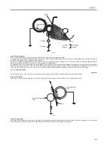
F-2-10
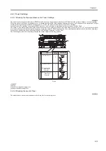
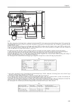
step 3:Å@development
This is where toner is put over the static image formed on the surface of the photosensitive drum.
As shown in the figure, the developing assembly is made up of a developing cylinder (which in turn consists of a fixed magnet and a cylinder that rotates
around it) and a rubber blade. It also holds toner inside it.
The toner is composed of magnetite and resins, and is held to the cylinder by means of magnetic force. The toner possesses insulating properties and is
charged to a negative potential as the result of friction against a rotating cylinder.
The potential of the area of the photosensitive drum that has been exposed by a laser beam is higher than that of the negatively charged toner on the cylinder;
thus, when the area comes close to the layer of the toner (possessing a negative potential) on the cylinder, the difference in potential between the drum
surface and the cylinder will cause the toner to move to the drum surface, turning the static image on the drum surface into a visible image.
2.4.1.5 Transfer Block
0008-0106
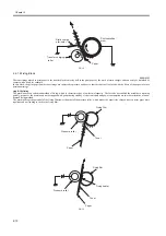
This block consists of 2 steps which are used to move the toner image on the surface of the photosensitive drum to print paper.
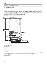
Step 4:Å@Transfer
In this step, a positive charge is applied to the back of print paper to attract toner from the surface of the photosensitive drum.
F-2-11
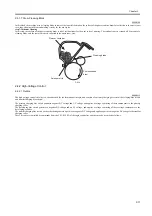
step 5:Å@separation
In this step, the machine takes advantage of the rigidity of print paper to detach it from the photosensitive drum. The static eliminator serves to decrease
the charge on the back of print paper, thus weakening the static bond of paper and facilitating the separation.
Stirrer
Blade
AC Bias
DC Bias
Cylinder
Magnet
Photosensitive
drum
Developing
cylinder
Paper
Transfer charging
roller
Photosensitive
drum
Summary of Contents for LBP-3000
Page 1: ...H T T P W W W F I X C L U B C O M C N Mar 10 2005 Service Manual LBP3000 2900 Series LBP2900 ...
Page 2: ...H T T P W W W F I X C L U B C O M C N ...
Page 6: ...H T T P W W W F I X C L U B C O M C N ...
Page 12: ...H T T P W W W F I X C L U B C O M C N Contents ...
Page 13: ...H T T P W W W F I X C L U B C O M C N Chapter 1 PRODUCT DESCRIPTION ...
Page 14: ...H T T P W W W F I X C L U B C O M C N ...
Page 16: ...H T T P W W W F I X C L U B C O M C N ...
Page 23: ...H T T P W W W F I X C L U B C O M C N Chapter 2 TECHNICAL REFERENCE ...
Page 24: ...H T T P W W W F I X C L U B C O M C N ...
Page 44: ...H T T P W W W F I X C L U B C O M C N Chapter 2 2 18 ...
Page 51: ...H T T P W W W F I X C L U B C O M C N Chapter 3 DISASSEMBLY AND ASSEMBLY ...
Page 52: ...H T T P W W W F I X C L U B C O M C N ...
Page 87: ...H T T P W W W F I X C L U B C O M C N Chapter 3 3 33 F 3 161 ...
Page 88: ...H T T P W W W F I X C L U B C O M C N ...
Page 89: ...H T T P W W W F I X C L U B C O M C N Chapter 4 MAINTENANCE AND INSPECTION ...
Page 90: ...H T T P W W W F I X C L U B C O M C N ...
Page 92: ...H T T P W W W F I X C L U B C O M C N ...
Page 98: ...H T T P W W W F I X C L U B C O M C N ...
Page 99: ...H T T P W W W F I X C L U B C O M C N Chapter 5 TROUBLESHOOTING ...
Page 100: ...H T T P W W W F I X C L U B C O M C N ...
Page 102: ...H T T P W W W F I X C L U B C O M C N ...
Page 107: ...H T T P W W W F I X C L U B C O M C N Chapter 6 APPENDIX ...
Page 108: ...H T T P W W W F I X C L U B C O M C N ...
Page 110: ...H T T P W W W F I X C L U B C O M C N ...
Page 117: ...H T T P W W W F I X C L U B C O M C N Mar 10 2005 ...

