HTTP://WWW.FIXCLUB.COM.CN
Chapter 2
2-16
up from the source.
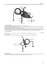
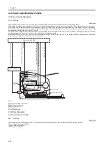
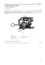
If paper is found in both trays, the machine uses the manual feed tray as the source of paper. The machine operates as follows to pick up paper from the
pickup tray/manual feed tray:
1. The engine controller turns on the main motor (M1) immediately after it receives the print command from the video controller. In response, the rollers
other than the pickup roller start to rotate.
2. When the initial rotation ready state (Note) starts, the pickup solenoid (SL1) goes on for about 0.2 sec, causing the rotation of the main motor to rotate
the pickup roller.
3. The pickup cam starts to rotate in keeping with the rotation of the pickup roller. The shape of the cam causes the spring to push up the holding plate.
The paper on the holding plate is picked up by the work of the pickup roller.
4. The engine controller sends the laser beam detection signal (/BD) to the video controller a specific period of time after the leading edge sensor (PS801)
detects the leading edge of print paper that has been picked up.
5. The video controller sends video signals to the laser/scanner assembly based on the /BD signal so as to form an image on the surface of the photosensitive
drum, making sure that the leading edge of the image and the leading edge of the print paper will match.
6. The print paper is then moved to the face-down tray for delivery by the work of the pressure roller and the face-down delivery roller.
When the initial rotation ready state:
The machine is in an initial rotation ready state when the main motor is on and, in addition, the fixing assembly temperature has reached a specific level
and the scanner motor has reached a specific revolution.
Summary of Contents for LBP-3000
Page 1: ...H T T P W W W F I X C L U B C O M C N Mar 10 2005 Service Manual LBP3000 2900 Series LBP2900 ...
Page 2: ...H T T P W W W F I X C L U B C O M C N ...
Page 6: ...H T T P W W W F I X C L U B C O M C N ...
Page 12: ...H T T P W W W F I X C L U B C O M C N Contents ...
Page 13: ...H T T P W W W F I X C L U B C O M C N Chapter 1 PRODUCT DESCRIPTION ...
Page 14: ...H T T P W W W F I X C L U B C O M C N ...
Page 16: ...H T T P W W W F I X C L U B C O M C N ...
Page 23: ...H T T P W W W F I X C L U B C O M C N Chapter 2 TECHNICAL REFERENCE ...
Page 24: ...H T T P W W W F I X C L U B C O M C N ...
Page 44: ...H T T P W W W F I X C L U B C O M C N Chapter 2 2 18 ...
Page 51: ...H T T P W W W F I X C L U B C O M C N Chapter 3 DISASSEMBLY AND ASSEMBLY ...
Page 52: ...H T T P W W W F I X C L U B C O M C N ...
Page 87: ...H T T P W W W F I X C L U B C O M C N Chapter 3 3 33 F 3 161 ...
Page 88: ...H T T P W W W F I X C L U B C O M C N ...
Page 89: ...H T T P W W W F I X C L U B C O M C N Chapter 4 MAINTENANCE AND INSPECTION ...
Page 90: ...H T T P W W W F I X C L U B C O M C N ...
Page 92: ...H T T P W W W F I X C L U B C O M C N ...
Page 98: ...H T T P W W W F I X C L U B C O M C N ...
Page 99: ...H T T P W W W F I X C L U B C O M C N Chapter 5 TROUBLESHOOTING ...
Page 100: ...H T T P W W W F I X C L U B C O M C N ...
Page 102: ...H T T P W W W F I X C L U B C O M C N ...
Page 107: ...H T T P W W W F I X C L U B C O M C N Chapter 6 APPENDIX ...
Page 108: ...H T T P W W W F I X C L U B C O M C N ...
Page 110: ...H T T P W W W F I X C L U B C O M C N ...
Page 117: ...H T T P W W W F I X C L U B C O M C N Mar 10 2005 ...

