HTTP://WWW.FIXCLUB.COM.CN
Chapter 2
2-11
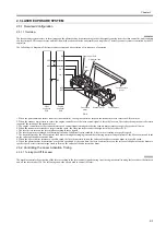
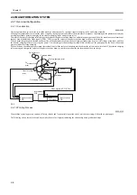
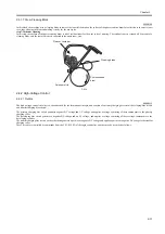
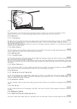
2.4.1.7 Drum Cleaning Block
0008-0108
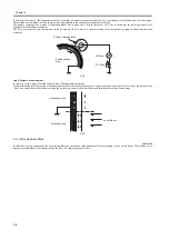
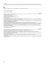
In this block, the machine uses a cleaning blade to remove the toner left behind on the surface of the photosensitive drum for collection to the waste toner
case, thus cleaning the drum and making it ready for the next cycle.
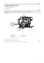
step 7:Å@drum cleaning
In this step, the surface of the photosensitive drum is rid of residual toner for the next cycle of printing. The residual toner is scraped off by means of a
cleaning blade, and the removed toner is collected in the waste toner case.
F-2-14
2.4.2 High-Voltage Control
2.4.2.1 Outline
0008-0111
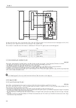
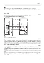
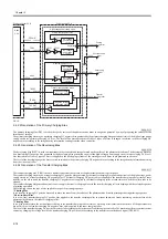
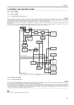
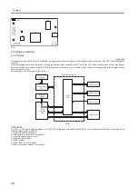
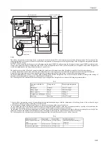
The high-voltage control circuitry is a circuit needed for the formation of images, and consists of a primary charging bias circuit, developing bias circuit,
and transfer charging bias circuit.
The primary charging bias circuit generates negative DC voltage and AC voltage, and applies a voltage consisting of these components to the primary
charging roller.
The developing bias circuit generates a negative DC voltage and an AC voltage, and applies a voltage consisting of these voltage components to the
developing cylinder.
The transfer charging bias circuit, on the other hand, generate a positive or negative DC voltage, and applies a positive or negative DC voltage to the transfer
charging roller.
These circuits are controlled by commands from the CPU (IC902) of the engine controller, and they may be described as follows:
Cleaner container
Sweeper strip
Photosensitive
drum
Cleaning blade
Summary of Contents for LBP-3000
Page 1: ...H T T P W W W F I X C L U B C O M C N Mar 10 2005 Service Manual LBP3000 2900 Series LBP2900 ...
Page 2: ...H T T P W W W F I X C L U B C O M C N ...
Page 6: ...H T T P W W W F I X C L U B C O M C N ...
Page 12: ...H T T P W W W F I X C L U B C O M C N Contents ...
Page 13: ...H T T P W W W F I X C L U B C O M C N Chapter 1 PRODUCT DESCRIPTION ...
Page 14: ...H T T P W W W F I X C L U B C O M C N ...
Page 16: ...H T T P W W W F I X C L U B C O M C N ...
Page 23: ...H T T P W W W F I X C L U B C O M C N Chapter 2 TECHNICAL REFERENCE ...
Page 24: ...H T T P W W W F I X C L U B C O M C N ...
Page 44: ...H T T P W W W F I X C L U B C O M C N Chapter 2 2 18 ...
Page 51: ...H T T P W W W F I X C L U B C O M C N Chapter 3 DISASSEMBLY AND ASSEMBLY ...
Page 52: ...H T T P W W W F I X C L U B C O M C N ...
Page 87: ...H T T P W W W F I X C L U B C O M C N Chapter 3 3 33 F 3 161 ...
Page 88: ...H T T P W W W F I X C L U B C O M C N ...
Page 89: ...H T T P W W W F I X C L U B C O M C N Chapter 4 MAINTENANCE AND INSPECTION ...
Page 90: ...H T T P W W W F I X C L U B C O M C N ...
Page 92: ...H T T P W W W F I X C L U B C O M C N ...
Page 98: ...H T T P W W W F I X C L U B C O M C N ...
Page 99: ...H T T P W W W F I X C L U B C O M C N Chapter 5 TROUBLESHOOTING ...
Page 100: ...H T T P W W W F I X C L U B C O M C N ...
Page 102: ...H T T P W W W F I X C L U B C O M C N ...
Page 107: ...H T T P W W W F I X C L U B C O M C N Chapter 6 APPENDIX ...
Page 108: ...H T T P W W W F I X C L U B C O M C N ...
Page 110: ...H T T P W W W F I X C L U B C O M C N ...
Page 117: ...H T T P W W W F I X C L U B C O M C N Mar 10 2005 ...

