HTTP://WWW.FIXCLUB.COM.CN
Chapter 2
2-12
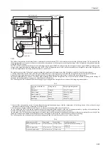
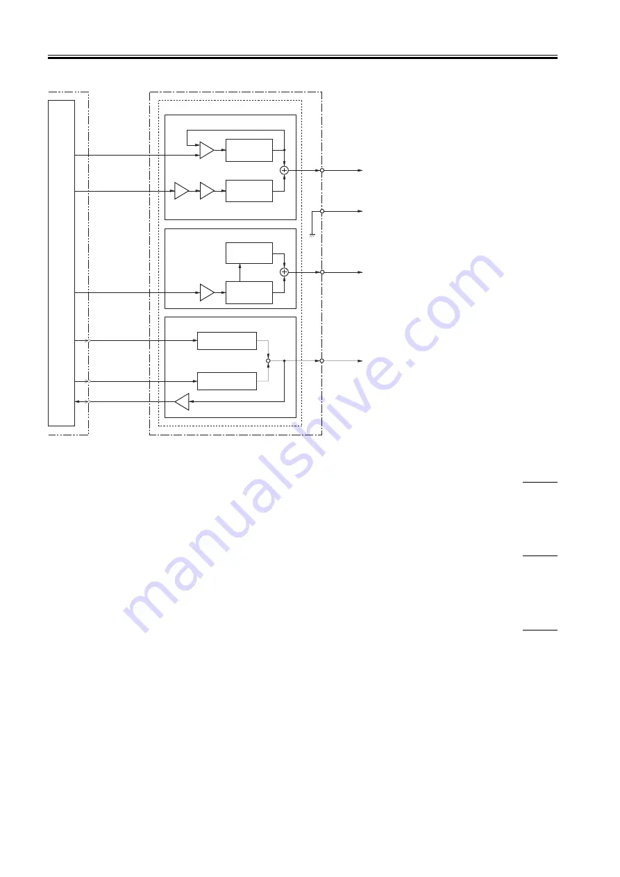
F-2-15
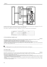
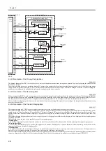
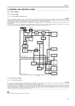
2.4.2.2 Generation of the Primary Charging Bias
0008-0113
The primary charging bias )PR1 is used to charge the surface of the photosensitive drum to a negative potential by way of preparing the surface for the
formation of images.
The primary charging bias may be a primary charging DC negative bias generated by the primary charging bias generation circuit of the high-voltage power
supply circuit )or a primary charging AC bias. The level of the bias that consists of these 2 types of biases is changed in relation to the developing DC
negative bias according to the image density information coming from the video controller.
2.4.2.3 Generation of the Developing Bias
0008-0115
The developing bias (DEV) is used to attract toner to the static (latent) image formed on the surface of the photosensitive drum. The developing bias may
be a developing DC negative bias generated by the developing bias generation circuit of the high-voltage power supply circuit or a developing AC bias. A
bias that consists of these 2 types of biases is applied to the developing cylinder of the cartridge at such times as programmed in advance.
The level of the developing negative bias is varied in relation to the primary charging DC negative bias according to the image density information arriving
from the video controller.
2.4.2.4 Generation of the Transfer Charging Bias
0008-0117
The transfer charging bias (TRS) is used to transfer toner from the surface of the photosensitive drum to print paper.
The transfer charging bias may be a transfer charging DC positive bias generated by the transfer charging bias generation circuit of the high-voltage power
supply circuit )or a transfer charging DC negative bias). The transfer charging DC positive bias is applied to the transfer charging roller at time of toner
transfer; on the other hand, the transfer charging DC negative bias is applied to the transfer charging roller at such times as when the roller needs to be
cleaned.
The transfer charging bias generation circuit serves to apply the transfer charging biases to the transfer charging roller in keeping with the selected sequence
of printing operation.
The following shows the type of bias applied for a specific printing sequence:
* Printing Bias
It is a transfer charging DC positive bias used to move the toner from the surface of the photosensitive drum to print paper during printing sequence.
* Sheet-to-Sheet Bias
It is a low level transfer charging DC positive bias applied to the transfer charging roller to prevent adhesion of toner remaining on the surface of the
photosensitive drum to the transfer charging roller.
* Cleaning Bias
It is a bias used to return the residual toner sticking to the transfer charging roller at time of warm-up or last rotation to the surface of the photosensitive
drum. This bias is a transfer charging DC negative bias, and is applied to the toner charging roller.
The level of the transfer charging DC positive bias is varied according to the instructions from the engine controller. The machine performs constant current
control by charging the voltage level of the transfer charging DC positive bias according to the transfer current feedback signal (TRCRNT).
PR1
TRS
DEV
IC902
CPU
DVAC
TRNDC
TRCRNT
TRPDC
PRAC
PRPWM
IC301
IC301
IC301
IC301
IC501
Positive voltage
generation circuit
J303
J304
J301
J302
DC voltage
generation
circuit
AC voltage
generation
circuit
DC voltage
generation
circuit
AC voltage
generation
circuit
Combined
Combined
Primary
charging roller
Developing
cylinder
Transfer
charging roller
Engine controller PCB
High-voltage power supply circuit
Developing bias circuit
Transfer charging bias circuit
Negative voltage
generation circuit
Photosensitive
drum
Primary charging bias circuit
J201-14
J902-10
J201-15
J902-9
J201-16
J902-8
J201-18
J902-6
J201-17
J902-7
J201-22
J902-2
Power supply PCB
Summary of Contents for LBP-3000
Page 1: ...H T T P W W W F I X C L U B C O M C N Mar 10 2005 Service Manual LBP3000 2900 Series LBP2900 ...
Page 2: ...H T T P W W W F I X C L U B C O M C N ...
Page 6: ...H T T P W W W F I X C L U B C O M C N ...
Page 12: ...H T T P W W W F I X C L U B C O M C N Contents ...
Page 13: ...H T T P W W W F I X C L U B C O M C N Chapter 1 PRODUCT DESCRIPTION ...
Page 14: ...H T T P W W W F I X C L U B C O M C N ...
Page 16: ...H T T P W W W F I X C L U B C O M C N ...
Page 23: ...H T T P W W W F I X C L U B C O M C N Chapter 2 TECHNICAL REFERENCE ...
Page 24: ...H T T P W W W F I X C L U B C O M C N ...
Page 44: ...H T T P W W W F I X C L U B C O M C N Chapter 2 2 18 ...
Page 51: ...H T T P W W W F I X C L U B C O M C N Chapter 3 DISASSEMBLY AND ASSEMBLY ...
Page 52: ...H T T P W W W F I X C L U B C O M C N ...
Page 87: ...H T T P W W W F I X C L U B C O M C N Chapter 3 3 33 F 3 161 ...
Page 88: ...H T T P W W W F I X C L U B C O M C N ...
Page 89: ...H T T P W W W F I X C L U B C O M C N Chapter 4 MAINTENANCE AND INSPECTION ...
Page 90: ...H T T P W W W F I X C L U B C O M C N ...
Page 92: ...H T T P W W W F I X C L U B C O M C N ...
Page 98: ...H T T P W W W F I X C L U B C O M C N ...
Page 99: ...H T T P W W W F I X C L U B C O M C N Chapter 5 TROUBLESHOOTING ...
Page 100: ...H T T P W W W F I X C L U B C O M C N ...
Page 102: ...H T T P W W W F I X C L U B C O M C N ...
Page 107: ...H T T P W W W F I X C L U B C O M C N Chapter 6 APPENDIX ...
Page 108: ...H T T P W W W F I X C L U B C O M C N ...
Page 110: ...H T T P W W W F I X C L U B C O M C N ...
Page 117: ...H T T P W W W F I X C L U B C O M C N Mar 10 2005 ...


