HTTP://WWW.FIXCLUB.COM.CN
Chapter 2
2-24
The term "long narrow paper" refers to a type of paper that is narrow in width and long in length.
2.8.2.2 Protective Functions
2.8.2.2.1 Protective Mechanisms
0008-0380
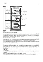
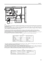
The machine is equipped with a protective mechanism in which the power to the heater is cut off upon detection of overheating of the fixing heater; the
mechanism used may be any of the following 3:
1. protection by means of the CPU
2. protection by means of the fixing heater safety circuit
3. protection by means of a thermal fuse
Specifically, these protective mechanisms operate as follows:
1. Protection by the CPU
The CPU monitors the voltage of the fixing heater temperature detection signal (FSRTH) from the thermistor at all times; if the fixing temperature
appreciably exceeds a specific level, it cuts off the power to the fixing heater.
In the event that the temperature of the fixing heater appreciably increases and the voltage of FSRTH is about 0.85 V or less (equivalent of 230 deg C) for
150 msec or if the level is about 1.17 V or less for 5 sec, the CPU causes the fixing heater drive signal (FSRD) to go Low to turn off the photo triac coupler
(SSR101), thus cutting off the power to the fixing heater.
2. Protection by the Fixing Heater Safety Circuit
The fixing heater safety circuit monitors the voltage of the fixing heater temperature signal (FSRTH) from the thermistor at all times; if the fixing
temperature appreciably exceeds a specific level, it cuts off the power to the fixing heater regardless of the instructions of the CPU.
In the event that the temperature of the fixing heater abnormally increases and the voltage of the fixing heater temperature detection signal (FSRTH) of
the thermistor is about 0.57 V or less (equivalent of 265 deg C), the output of the comparator (IC501) goes Low to turn off the transistor (Q103). The fact
will cause the relay (RL101) to go off to cut off the power to the fixing heater regardless of the state of the relay drive signal (RLYD) from the CPU.
3. Protection by a Thermal Fuse
If the temperature of the fixing heater abnormally increase and the temperature of the thermal fuse (FU1) exceeds about 30 deg C, the thermal fuse will
melt to cut of the power to the fixing heater.
2.8.2.2.2 Detection of a Fault
0008-0383
The CPU will assume the presence of a fault in the fixing assembly in response to any of the following 7 conditions; it will turn off the relay (RL101) to
cut out the power to the heater and, at the same time, will communicate the fact to the video controller:
1. the temperature of the thermistor does not exceeded 50 deg C within 1.47 sec after the start of temperature control.
2. it monitors the temperature of the thermistor every 5 msec; if the temperature of the thermistor is 230 deg C or more 30 times continuously.
3. it monitors the temperature of the thermistor every 5 msec; if the temperature is 100 deg C or less at time of normal temperature control (or 5 deg C or
less at time of cleaning mode) 240 times continuously.
4. after the temperature of the thermistor has exceeded 50 deg C, it monitors the temperature of the thermistor every 5 msec; if it the temperature is less
than 20 deg C 60 times continuously.
5. the temperature of the thermistor does not reach 100 deg C within 30 sec after supply of power to the fixing heater has started.
6. while the paper is retained by the fixing assembly, it monitors the temperature of the thermistor every 200 msec; if the temperature is 120 deg C or more
25 times continuously.
7. while the paper is retained in the fixing assembly; it monitors the temperature of the thermistor every 200 msec; if the temperature is less tan 135 deg C
150 times continuously
Summary of Contents for LBP-3000
Page 1: ...H T T P W W W F I X C L U B C O M C N Mar 10 2005 Service Manual LBP3000 2900 Series LBP2900 ...
Page 2: ...H T T P W W W F I X C L U B C O M C N ...
Page 6: ...H T T P W W W F I X C L U B C O M C N ...
Page 12: ...H T T P W W W F I X C L U B C O M C N Contents ...
Page 13: ...H T T P W W W F I X C L U B C O M C N Chapter 1 PRODUCT DESCRIPTION ...
Page 14: ...H T T P W W W F I X C L U B C O M C N ...
Page 16: ...H T T P W W W F I X C L U B C O M C N ...
Page 23: ...H T T P W W W F I X C L U B C O M C N Chapter 2 TECHNICAL REFERENCE ...
Page 24: ...H T T P W W W F I X C L U B C O M C N ...
Page 44: ...H T T P W W W F I X C L U B C O M C N Chapter 2 2 18 ...
Page 51: ...H T T P W W W F I X C L U B C O M C N Chapter 3 DISASSEMBLY AND ASSEMBLY ...
Page 52: ...H T T P W W W F I X C L U B C O M C N ...
Page 87: ...H T T P W W W F I X C L U B C O M C N Chapter 3 3 33 F 3 161 ...
Page 88: ...H T T P W W W F I X C L U B C O M C N ...
Page 89: ...H T T P W W W F I X C L U B C O M C N Chapter 4 MAINTENANCE AND INSPECTION ...
Page 90: ...H T T P W W W F I X C L U B C O M C N ...
Page 92: ...H T T P W W W F I X C L U B C O M C N ...
Page 98: ...H T T P W W W F I X C L U B C O M C N ...
Page 99: ...H T T P W W W F I X C L U B C O M C N Chapter 5 TROUBLESHOOTING ...
Page 100: ...H T T P W W W F I X C L U B C O M C N ...
Page 102: ...H T T P W W W F I X C L U B C O M C N ...
Page 107: ...H T T P W W W F I X C L U B C O M C N Chapter 6 APPENDIX ...
Page 108: ...H T T P W W W F I X C L U B C O M C N ...
Page 110: ...H T T P W W W F I X C L U B C O M C N ...
Page 117: ...H T T P W W W F I X C L U B C O M C N Mar 10 2005 ...

