background image

HTTP://WWW.FIXCLUB.COM.CN

Chapter 3

3-9

F-3-40

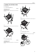
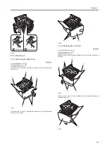
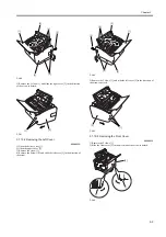
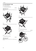
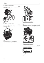
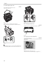
5) Remove the 3 claws [1], and slide the right cover [2] in the direction

of the arrow to detach.

F-3-41

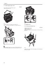
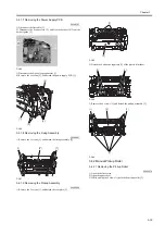
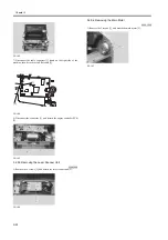
3.1.10.2 Removing the Left Cover

0008-3572

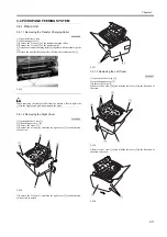
1) Open the delivery tray [1].

2) Open the upper cover [2].

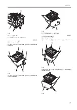
3) Remove the screw [3].

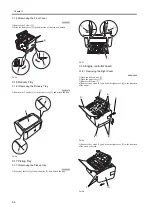
4) Remove the 4 claws [4], and slide the left cover [5] in the direction of

the arrow.

F-3-42

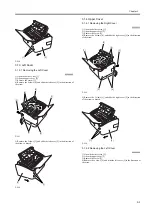
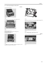
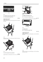
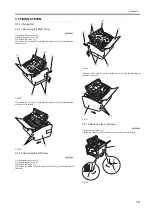
5) Remove the 3 claws [1], and slide the left cover [2] in the direction of

the arrow to detach.

F-3-43

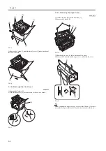
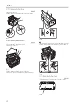
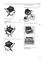
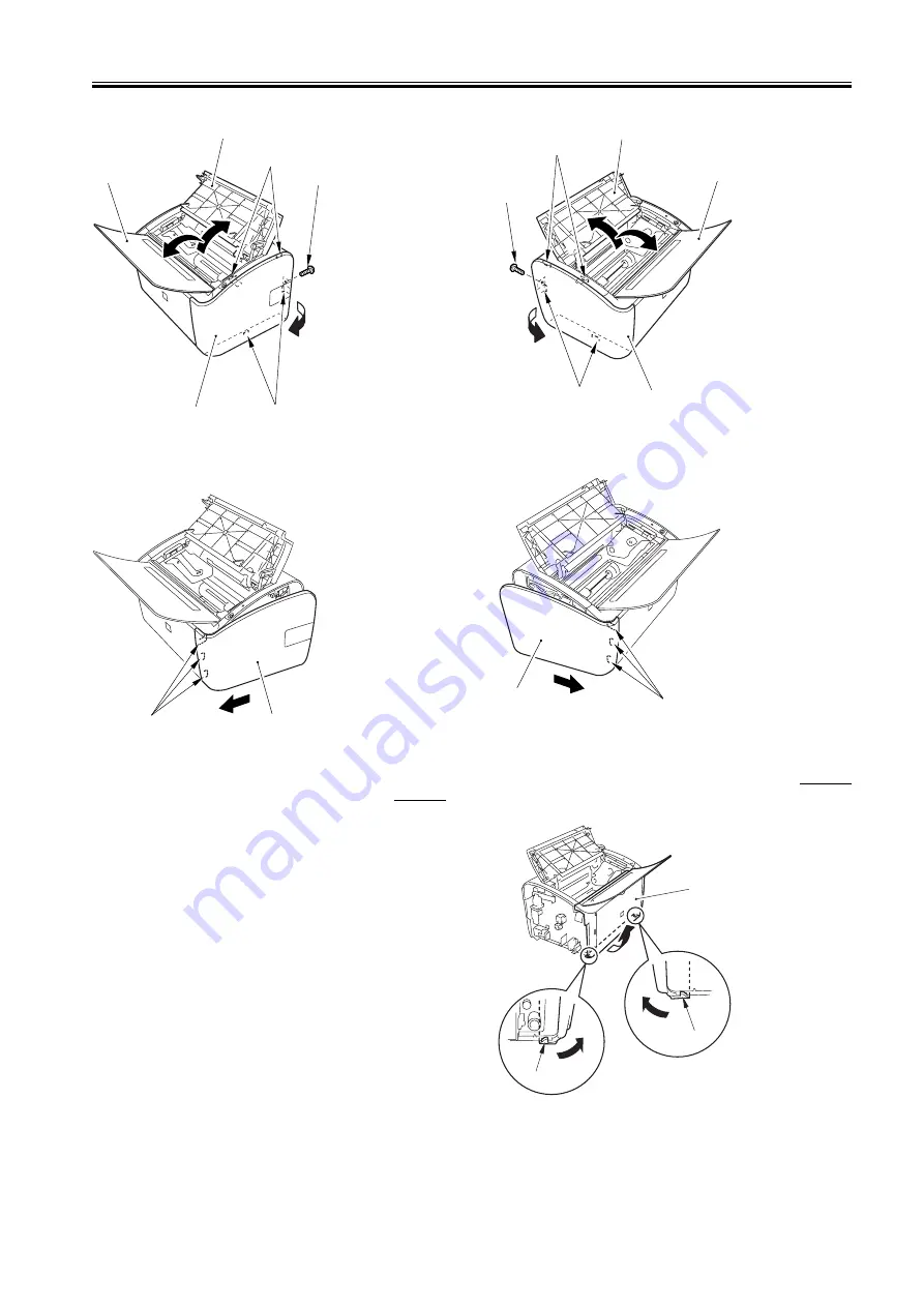
3.1.10.3 Removing the Front Cover

0008-3573

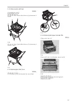
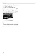
1) Remove the 2 claws [1].

2) Slide the front cover [2] in the direction of the arrow to detach.

F-3-44

[1]

[2]

[3]

[4]

[4]

[5]

[1]

[2]

[1]

[2]

[3]

[4]

[4]

[5]

[1]

[2]

[1]

[1]

[2]

Summary of Contents for LBP-3000

Page 1: ...H T T P W W W F I X C L U B C O M C N Mar 10 2005 Service Manual LBP3000 2900 Series LBP2900 ...

Page 2: ...H T T P W W W F I X C L U B C O M C N ...

Page 3: ... information as the need arises In the event of major changes in the contents of this manual over a long or short period Canon will issue a new edition of this manual The following paragraph does not apply to any countries where such provisions are inconsistent with local law Trademarks The product names and company names used in this manual are the registered trademarks of the individual companie...

Page 4: ...ndicates an item requiring care to avoid combustion fire Indicates an item prohibiting disassembly to avoid electric shocks or problems Indicates an item requiring disconnection of the power plug from the electric outlet Indicates an item intended to provide notes assisting the understanding of the topic in question Indicates an item of reference assisting the understanding of the topic in questio...

Page 5: ... is High while 0 is used to indicate Low The voltage value however differs from circuit to circuit In addition the asterisk as in DRMD indicates that the DRMD signal goes on when 0 In practically all cases the internal mechanisms of a microprocessor cannot be checked in the field Therefore the operations of the microprocessors used in the machines are not discussed they are explained in terms of f...

Page 6: ...H T T P W W W F I X C L U B C O M C N ...

Page 7: ...Controlling the Laser Activation Timing 2 3 2 3 2 1 Turning On Off the Laser 2 3 2 3 2 2 Horizontal Synchronization Control 2 4 2 3 3 Laser Control 2 4 2 3 3 1 Auto Photo Current Control 2 4 2 3 4 Laser Scanner Motor Control 2 5 2 3 4 1 Outline 2 5 2 3 4 2 Scanner Motor Speed Control 2 5 2 3 4 3 Detection of a Fault in the Scanner Motor 2 5 2 4 IMAGE FORMATION SYSTEM 2 6 2 4 1 Overview Configurati...

Page 8: ...Temperature Control 2 22 2 8 2 2 Protective Functions 2 24 Chapter 3 DISASSEMBLY AND ASSEMBLY 3 1 EXTERNAL AND CONTROLS SYSTEM 3 1 3 1 1 Rear Cover 3 1 3 1 1 1 Removing the Right Cover 3 1 3 1 1 2 Removing the Left Cover 3 1 3 1 1 3 Removing the Front Cover 3 1 3 1 1 4 Removing the Upper Cover 3 2 3 1 2 Right Cover 3 2 3 1 2 1 Removing the Right Cover 3 2 3 1 3 Left Cover 3 3 3 1 3 1 Removing the ...

Page 9: ...Pickup Unit 3 17 3 4 1 1 Removing the Transfer Charging Roller 3 17 3 4 1 2 Removing the Right Cover 3 17 3 4 1 3 Removing the Left Cover 3 17 3 4 1 4 Removing the Front Cover 3 18 3 4 1 5 Removing the Upper Cover 3 18 3 4 1 6 Removing the Rear Cover 3 18 3 4 1 7 Removing the Power Supply PCB 3 19 3 4 1 8 Removing the Fixing Assembly 3 19 3 4 1 9 Removing the Pickup Assembly 3 19 3 4 2 Manual Pick...

Page 10: ...the Right Cover 3 30 3 5 4 2 Removing the Left Cover 3 31 3 5 4 3 Removing the Front Cover 3 31 3 5 4 4 Removing the Upper Cover 3 32 3 5 4 5 Removing the Rear Cover 3 32 3 5 4 6 Removing the Delivery Sensor 3 32 Chapter 4 MAINTENANCE AND INSPECTION 4 1 Periodically Replaced Parts 4 1 4 1 1 Periodic Replacement Parts 4 1 4 2 Consumables 4 2 4 2 1 Consumable Parts 4 2 4 3 Periodical Service 4 3 4 3...

Page 11: ...X C L U B C O M C N Contents 6 1 2 Motor 6 2 6 1 2 1 Motor 6 2 6 1 3 Sensor 6 3 6 1 3 1 Sensor 6 3 6 1 4 Switch 6 4 6 1 4 1 Switch 6 4 6 1 5 Lamps Heaters and Others 6 5 6 1 5 1 Heater 6 5 6 1 6 PCBs 6 6 6 1 6 1 PCBs 6 6 ...

Page 12: ...H T T P W W W F I X C L U B C O M C N Contents ...

Page 13: ...H T T P W W W F I X C L U B C O M C N Chapter 1 PRODUCT DESCRIPTION ...

Page 14: ...H T T P W W W F I X C L U B C O M C N ...

Page 15: ...ine Specifications 1 2 1 3 Name of Parts 1 3 1 3 1 External View 1 3 1 3 2 Cross Section View 1 3 1 4 Using the Machine 1 5 1 4 1 Control Panel 1 5 1 5 Safety 1 6 1 5 1 Safety of Laser Light 1 6 1 5 2 Regulations Under the Center for Devices and Radiological Health CDRH 1 6 1 5 3 Safety of Toner 1 6 1 5 4 Handling the Laser Unit 1 6 ...

Page 16: ...H T T P W W W F I X C L U B C O M C N ...

Page 17: ... in design perfectly suited for installation on a desk and yet it is a mono color printer capable of turning out as many as 12 0 prints A4 every minute 2 Shorter Wait Time and Lower Power Consumption The machine uses an on demand fixing method enabling a shorter wait time and lower power consumption when compared with machines that use a roller fixing method ...

Page 18: ...5 LGL LTR Executive postcard envelope user defined paper 76 2 to 215 9 mm in width 127 to 355 6 mm in length Cassette paper type plain paper 64 to 90 g m2 heavy paper 91 to 163 g m2 recycled paper transparency label sheet postcard envelope Multi purpose paper type plain paper 64 to 90 g m2 heavy paper 91 to 163 g m2 recycled paper transparency label sheet postcard envelope Cassette capacity if pla...

Page 19: ... 1 1 3 1 3 Name of Parts 1 3 1 External View 0009 2753 F 1 1 T 1 1 1 3 2 Cross Section View 0007 6027 F 1 2 1 Rear cover 6 Left cover 2 Upper cover 7 Right cover 3 Delivery tray 4 Pickup tray 5 Front cover 2 3 4 5 6 1 7 1 2 3 4 5 6 7 8 9 10 11 12 ...

Page 20: ...T 1 2 1 Photosensitive drum 8 Developing cylinder 2 Pressure roller 9 Pickup roller 3 Fixing film assembly 10 Separation pad 4 Delivery roller 11 Feed roller 5 Primary charging roller 12 Transfer charging roller 6 Toner cartridge 7 Laser scanner assembly ...

Page 21: ...lied with power OFF indicates that the machine is not supplied with power 2 Paper Lamp flashing indicates the absence of paper or the presence of a jam while a job is under way OFF indicates the presence of a service error or the presence of a state other than the above 3 Paper Key A press on this key after supplying paper or removing the jam will cause the machine to resume the suspended printing...

Page 22: ...n or Clothes 1 If your skin or clothes came into contact with toner use dry tissue to remove the toner and then wash with water 2 Do not use warm or hot water which will cause the toner to jell permanently fusing it with the fibers of the clothes 3 Do not bring toner into contact with vinyl material They are likely to react with each other 1 5 4 Handling the Laser Unit 0007 6038 The laser scanner ...

Page 23: ...H T T P W W W F I X C L U B C O M C N Chapter 2 TECHNICAL REFERENCE ...

Page 24: ...H T T P W W W F I X C L U B C O M C N ...

Page 25: ... 2 4 1 6 Fixing Block 2 10 2 4 1 7 Drum Cleaning Block 2 11 2 4 2 High Voltage Control 2 11 2 4 2 1 Outline 2 11 2 4 2 2 Generation of the Primary Charging Bias 2 12 2 4 2 3 Generation of the Developing Bias 2 12 2 4 2 4 Generation of the Transfer Charging Bias 2 12 2 4 3 Toner Cartridge 2 13 2 4 3 1 Checking the Presence Absence of a Toner Cartridge 2 13 2 4 3 2 Checking the Level of Toner 2 13 2...

Page 26: ... 1 Overview 2 19 2 7 1 2 Outline of Operation by Block 2 19 2 7 2 Engine Controller 2 20 2 7 2 1 Outline 2 20 2 8 FIXING UNIT DELIVERY SYSTEM 2 21 2 8 1 Overview Configuration 2 21 2 8 1 1 Overview 2 21 2 8 1 2 Major Components of the Fixing Assembly 2 21 2 8 2 Various Control Mechanisms 2 22 2 8 2 1 Fixing Temperature Control 2 22 2 8 2 1 1 Heater Temperature Control 2 22 2 8 2 2 Protective Funct...

Page 27: ... divided into 6 blocks the engine control system laser exposure system image formation system pickup and feed system fixing and delivery system external and control system F 2 1 To external devices Engine control system Laser exposure system Pickup and feed system Image formation system Fixing and delivery system External and control system ...

Page 28: ...ove Period Purpose Remarks WAIT Wait From power ON until the end of the main motor initial rotation To clean the drum surface of potential and to clean the transfer charging roller Toner cartridge in out detection is executed STBY Standby From the end of the WAIT period or the LSTR period until the input of the pick up command from the video controller Or from the end of the LSTR period until powe...

Page 29: ...nals to the laser driver PCB 5 The laser driver turns on the laser diode according to these signals 6 The laser beam moves through a collimating lens and a cylindrical lens to reach the 4 facet mirror rotating at a specific speed 7 The beam reflected by the 4 facet mirror then moves through the imaging lens and the reflecting mirror arranged in front of the 4 facet mirror and focus on the surface ...

Page 30: ... is turned on in a non image area 2 3 3 Laser Control 2 3 3 1 Auto Photo Current Control 0008 0094 The machine executes auto photo current control to make sure that the laser diode emits light at a specific level of intensity APC may be either initial APC Note 1 which is executed during initial rotation or interval APC Note 2 which is executed during printing however both of them are executed in t...

Page 31: ...ling the rotation of the scanner motor 2 3 4 3 Detection of a Fault in the Scanner Motor 0008 0097 The CPU of the engine controller monitors the frequency comparator to find out whether the scanner motor is rotating at a specific speed The CPU will assume any of the following conditions to be a fault or error in the scanner motor and stop the engine while at the same time communicating the fact to...

Page 32: ...into a visible image using toner and then the transfer charging roller moves it to print paper The toner image is then fused permanently into the fibers of the print paper by the work of heat and pressure inside the fixing assembly When all is done the cleaning blade scrapes the residual toner off the surface of the photosensitive drum for collection as waste toner The primary charging roller once...

Page 33: ...t paper step 6 Å fixing 5 Å Drum Cleaning Block In this block the residual toner left on the photosensitive drum is removed for collection as waste toner step 7 Å drum cleaning in which residual toner is removed from the photosensitive drum 2 4 1 3 Latent Image Formation Block 0008 0103 This block consists of 2 steps during which a static image is formed on the surface of the photosensitive drum A...

Page 34: ...y signal coming from the video controller F 2 8 step 2 Å laser beam exposure In this step a static image is formed on the surface of the photosensitive drum When the machine scans the surface of the photosensitive drum that has been charged to a negative potential by means of a laser beam the charges in the light area become neutralized thus removing the negative potential of the drum surface and ...

Page 35: ...omes close to the layer of the toner possessing a negative potential on the cylinder the difference in potential between the drum surface and the cylinder will cause the toner to move to the drum surface turning the static image on the drum surface into a visible image 2 4 1 5 Transfer Block 0008 0106 This block consists of 2 steps which are used to move the toner image on the surface of the photo...

Page 36: ...es an on demand method of fixing which is characterized by a low thermal capacity The fact also has enabled the machine to warm up quickly moreover the heater need not be supplied with power during standby A short wait time and power consumption are two characteristics of an on demand fixing method The machine keeps the potential of the fixing film lower than that of the pressure roller which make...

Page 37: ...rcuitry is a circuit needed for the formation of images and consists of a primary charging bias circuit developing bias circuit and transfer charging bias circuit The primary charging bias circuit generates negative DC voltage and AC voltage and applies a voltage consisting of these components to the primary charging roller The developing bias circuit generates a negative DC voltage and an AC volt...

Page 38: ...toner transfer on the other hand the transfer charging DC negative bias is applied to the transfer charging roller at such times as when the roller needs to be cleaned The transfer charging bias generation circuit serves to apply the transfer charging biases to the transfer charging roller in keeping with the selected sequence of printing operation The following shows the type of bias applied for ...

Page 39: ... The sensor is also used to detect the width of paper in the course of a print job When a sheet other than of a small size i e 197 mm or more in width moves past the paper width detecting lever operates causing the output of PS802 to change and thus enabling the machine to check the width of the sheet In the case of a small size sheet the output of PS802 will be High otherwise it will be Low The f...

Page 40: ...hether print paper has reached or has moved past a specific point of the paper path If print paper fails to reach or move past a specific point within a specific period of time the CPU of the engine controller will identify the condition as being a jam and communicate the fact to the video controller F 2 17 PS801 paper leading edge sensor PS802 paper width sensor PS803 delivery sensor M1 main moto...

Page 41: ...assume the presence of a pickup stationary jam if the paper width sensor PS802 does not detect the trailing edge of paper within 200 msec after the paper width sensor PS802 has detected the leading edge of paper and the paper leading edge sensor PS801 has detected the trailing edge of paper 2 5 2 3 2 Delivery Stationary Jam 0008 0157 The CPU will assume the presence of a delivery stationary jam if...

Page 42: ...the holding plate The paper on the holding plate is picked up by the work of the pickup roller 4 The engine controller sends the laser beam detection signal BD to the video controller a specific period of time after the leading edge sensor PS801 detects the leading edge of print paper that has been picked up 5 The video controller sends video signals to the laser scanner assembly based on the BD s...

Page 43: ...0493 The protective mechanisms include an overcurrent protective circuit that uses a fuse If short circuit or the like occurs because of some fault and as a result an overcurrent flows the fuses will melt to cut off the power to the power supply circuit The power supply circuit is equipped with 2 fuses Note FU101 FU102 in the event an overcurrent flows into the AC line either of these fuses will m...

Page 44: ...H T T P W W W F I X C L U B C O M C N Chapter 2 2 18 ...

Page 45: ... and erasing of it electrically It is used to retain parameters of the printer unit that must remain unchanged e g USB serial number printing environment these parameters are retained when the power is turned off on 2 ASIC IC2 It has the following functions 1 controls the input output of the internal RAM 2 controls the timing at which dot pattern data is sent to the engine controller 3 decompresse...

Page 46: ...cording to the print command coming from the video controller The following is a block diagram of the circuit F 2 22 CPU IC902 The CPU is a 8 bit single chip microprocessor IC The CPU is equipped with both ROM and RAM and it performs the following as instructed by the control program stored in the ROM 1 sequential control of the printer 2 communicates with the interface controller 3 controls the p...

Page 47: ...ater and the pressure from the pressure roller to permanently fuse the toner with the fibers of the print paper before it moves out of the fixing assembly Once outside the fixing assembly the print paper is delivered to the delivery tray by the work of the face down delivery roller upon detection by the delivery sensor PS803 F 2 23 T 2 3 2 8 1 2 Major Components of the Fixing Assembly 0008 0914 Th...

Page 48: ...e target temperature Heater There is a single heater fixing heater H1 used to heat the fixing film ceramic heater Thermistor There is a single thermistor main thermistor TH1 used for the control of the temperature of the fixing heater non contact thermistor Thermal fuse There is a single thermal fuse thermal fuse TP1 used to detect overheating of the fixing heater non contact fuse The thermal fuse...

Page 49: ...us printing so that the temperature of the fixing heater is lower than the target temperature thus preventing overheating of the fixing film 4 down sequence during continuous printing so as to prevent overheating of the edges of the heater In this control the CPU of the engine controller checks the length and width of paper if the size of the paper matches a specific set of conditions the machine ...

Page 50: ...57 V or less equivalent of 265 deg C the output of the comparator IC501 goes Low to turn off the transistor Q103 The fact will cause the relay RL101 to go off to cut off the power to the fixing heater regardless of the state of the relay drive signal RLYD from the CPU 3 Protection by a Thermal Fuse If the temperature of the fixing heater abnormally increase and the temperature of the thermal fuse ...

Page 51: ...H T T P W W W F I X C L U B C O M C N Chapter 3 DISASSEMBLY AND ASSEMBLY ...

Page 52: ...H T T P W W W F I X C L U B C O M C N ...

Page 53: ...Cover 3 7 3 1 8 3 Removing the Front Cover 3 7 3 1 8 4 Removing the Engine Controller PCB 3 7 3 1 9 Video Controller Board 3 8 3 1 9 1 Removing the Right Cover 3 8 3 1 10 Power supply board 3 8 3 1 10 1 Removing the Right Cover 3 8 3 1 10 2 Removing the Left Cover 3 9 3 1 10 3 Removing the Front Cover 3 9 3 1 10 4 Removing the Upper Cover 3 10 3 1 10 5 Removing the Rear Cover 3 10 3 1 10 6 Removin...

Page 54: ... Removing the Right Cover 3 23 3 5 1 2 Removing the Left Cover 3 23 3 5 1 3 Removing the Front Cover 3 23 3 5 1 4 Removing the Upper Cover 3 24 3 5 1 5 Removing the Rear Cover 3 24 3 5 1 6 Removing the Power Supply PCB 3 24 3 5 1 7 Removing the Fixing Assembly 3 25 3 5 2 Fixing Film Unit 3 25 3 5 2 1 Removing the Right Cover 3 25 3 5 2 2 Removing the Left Cover 3 25 3 5 2 3 Removing the Front Cove...

Page 55: ...e the right cover 2 in the direction of the arrow to detach F 3 2 3 1 1 2 Removing the Left Cover 0008 3538 1 Open the delivery tray 1 2 Open the upper cover 2 3 Remove the screw 3 4 Remove the 4 claws 4 and slide the left cover 5 in the direction of the arrow F 3 3 5 Remove the 3 claws 1 and slide the left cover 2 in the direction of the arrow to detach F 3 4 3 1 1 3 Removing the Front Cover 0008...

Page 56: ...nting the upper cover be sure to fit the 2 hooks 2 used to release the fixing assembly in the 2 hook holes 1 found in the cover F 3 8 3 1 2 Right Cover 3 1 2 1 Removing the Right Cover 0008 0965 1 Open the delivery tray 1 2 Open the upper cover 2 3 Remove the screw 3 4 Remove the 4 claws 4 and slide the right cover 5 in the direction of the arrow F 3 9 5 Remove the 3 claws 1 and slide the right co...

Page 57: ...etach F 3 12 3 1 4 Upper Cover 3 1 4 1 Removing the Right Cover 0008 3533 1 Open the delivery tray 1 2 Open the upper cover 2 3 Remove the screw 3 4 Remove the 4 claws 4 and slide the right cover 5 in the direction of the arrow F 3 13 5 Remove the 3 claws 1 and slide the right cover 2 in the direction of the arrow to detach F 3 14 3 1 4 2 Removing the Left Cover 0008 3534 1 Open the delivery tray ...

Page 58: ...e direction of the arrow to detach F 3 17 3 1 4 4 Removing the Upper Cover 0008 0971 1 Free the link stop 2 from the door link 1 2 Remove the 2 screws 3 F 3 18 3 Slide the upper cover 1 in the direction of the arrow 4 Remove the 2 claws 2 of the upper cover and detach the cover F 3 19 When mounting the upper cover be sure to fit the 2 hooks 2 used to release the fixing assembly in the 2 hook holes...

Page 59: ...ow F 3 21 5 Remove the 3 claws 1 and slide the right cover 2 in the direction of the arrow to detach F 3 22 3 1 5 2 Removing the Left Cover 0008 3532 1 Open the delivery tray 1 2 Open the upper cover 2 3 Remove the screw 3 4 Remove the 4 claws 4 and slide the left cover 5 in the direction of the arrow F 3 23 5 Remove the 3 claws 1 and slide the left cover 2 in the direction of the arrow to detach ...

Page 60: ...h the tray F 3 26 3 1 7 Pickup Tray 3 1 7 1 Removing the Pickup Tray 0008 0969 1 Free the 2 shafts 1 of the pickup tray 2 and detach the tray F 3 27 3 1 8 Engine controller board 3 1 8 1 Removing the Right Cover 0008 3542 1 Open the delivery tray 1 2 Open the upper cover 2 3 Remove the screw 3 4 Remove the 4 claws 4 and slide the right cover 5 in the direction of the arrow F 3 28 5 Remove the 3 cl...

Page 61: ...eft cover 2 in the direction of the arrow to detach F 3 31 3 1 8 3 Removing the Front Cover 0008 3544 1 Remove the 2 claws 1 2 Slide the front cover 2 in the direction of the arrow to detach F 3 32 3 1 8 4 Removing the Engine Controller PCB 0008 1113 1 Remove the 4 screws 1 F 3 33 2 Remove the 2 claws 1 and detach the scanner cover 2 F 3 34 3 Free the 2 flat cables 1 4 While pushing on the pin 2 f...

Page 62: ...0008 7939 1 Open the delivery tray 1 2 Open the upper cover 2 3 Remove the screw 3 4 Remove the 4 claws 4 and slide the right cover 5 in the direction of the arrow F 3 38 5 Remove the 3 claws 1 and slide the right cover 2 in the direction of the arrow to detach F 3 39 3 1 10 Power supply board 3 1 10 1 Removing the Right Cover 0008 3571 1 Open the delivery tray 1 2 Open the upper cover 2 3 Remove ...

Page 63: ...ery tray 1 2 Open the upper cover 2 3 Remove the screw 3 4 Remove the 4 claws 4 and slide the left cover 5 in the direction of the arrow F 3 42 5 Remove the 3 claws 1 and slide the left cover 2 in the direction of the arrow to detach F 3 43 3 1 10 3 Removing the Front Cover 0008 3573 1 Remove the 2 claws 1 2 Slide the front cover 2 in the direction of the arrow to detach F 3 44 1 2 3 4 4 5 1 2 1 2...

Page 64: ...e to fit the 2 hooks 2 used to release the fixing assembly in the 2 hook holes 1 found in the cover F 3 47 3 1 10 5 Removing the Rear Cover 0008 3575 1 Slide the rear cover 1 in the direction of the arrow to detach F 3 48 3 1 10 6 Removing the Power Supply PCB 0008 1107 1 Disconnect the flat cable 1 2 Disconnect the 4 connectors 2 and free the harness 4 from the harness guide 3 F 3 49 3 Disconnect...

Page 65: ...ion of the arrow F 3 51 5 Remove the 3 claws 1 and slide the right cover 2 in the direction of the arrow to detach F 3 52 3 1 11 2 Removing the Left Cover 0008 3577 1 Open the delivery tray 1 2 Open the upper cover 2 3 Remove the screw 3 4 Remove the 4 claws 4 and slide the left cover 5 in the direction of the arrow F 3 53 5 Remove the 3 claws 1 and slide the left cover 2 in the direction of the a...

Page 66: ...link 1 2 Remove the 2 screws 3 F 3 56 3 Slide the upper cover 1 in the direction of the arrow 4 Remove the 2 claws 2 of the upper cover and detach the cover F 3 57 When mounting the upper cover be sure to fit the 2 hooks 2 used to release the fixing assembly in the 2 hook holes 1 found in the cover F 3 58 3 1 11 5 Removing the Rear Cover 0008 3580 1 Slide the rear cover 1 in the direction of the a...

Page 67: ... Leading Edge Paper Width Sensor PCB 0008 1122 1 Disconnect the connector 1 and free the harness 3 from the harness guide 2 F 3 60 2 Remove the 2 screws 1 and detach the rear plate 2 F 3 61 3 Remove the 2 claws 1 and detach the paper leading edge paper width sensor PCB 2 F 3 62 1 2 ...

Page 68: ... the right cover 2 in the direction of the arrow to detach F 3 64 3 2 1 2 Removing the Left Cover 0008 3549 1 Open the delivery tray 1 2 Open the upper cover 2 3 Remove the screw 3 4 Remove the 4 claws 4 and slide the left cover 5 in the direction of the arrow F 3 65 5 Remove the 3 claws 1 and slide the left cover 2 in the direction of the arrow to detach F 3 66 3 2 1 3 Removing the Front Cover 00...

Page 69: ...s 1 4 While pushing on the pin 2 free the cable guide 3 5 Disconnect the connector 4 6 Remove the screw 5 F 3 70 7 Disconnect the cable connector 1 found on the right side of the machine then detach the full flat cable 2 F 3 71 8 Disconnect the connector 1 and detach the engine controller PCB 2 F 3 72 3 2 1 5 Removing the Laser Scanner Unit 0008 1063 1 Remove the 4 screws 1 and detach the laser sc...

Page 70: ...y 2 Open the upper cover 3 Remove the 2 claws 1 of the transfer charging roller 4 Remove the 2 claws 2 of the transfer guide 5 Detach the transfer charging roller 4 together with the transfer guide 3 6 Detach the transfer charging roller 4 from the transfer guide 3 F 3 74 When removing the transfer roller from the machine free its right side 1 in the figure and pull it out toward the right ...

Page 71: ...e free its right side 1 in the figure and pull it out toward the right 3 4 1 2 Removing the Right Cover 0008 3586 1 Open the delivery tray 1 2 Open the upper cover 2 3 Remove the screw 3 4 Remove the 4 claws 4 and slide the right cover 5 in the direction of the arrow F 3 76 5 Remove the 3 claws 1 and slide the right cover 2 in the direction of the arrow to detach F 3 77 3 4 1 3 Removing the Left C...

Page 72: ...ink 1 2 Remove the 2 screws 3 F 3 81 3 Slide the upper cover 1 in the direction of the arrow 4 Remove the 2 claws 2 of the upper cover and detach the cover F 3 82 When mounting the upper cover be sure to fit the 2 hooks 2 used to release the fixing assembly in the 2 hook holes 1 found in the cover F 3 83 3 4 1 6 Removing the Rear Cover 0008 3590 1 Slide the rear cover 1 in the direction of the arr...

Page 73: ...ng the Fixing Assembly 0008 3591 1 Remove the 3 screws 1 and detach the fixing assembly 2 F 3 87 3 4 1 9 Removing the Pickup Assembly 0008 1059 1 Remove the 2 screws 1 and detach the rear plate 2 F 3 88 2 Detach the 6 adhesive segments 1 of the plastic film sheet F 3 89 3 Remove the 6 screws 1 and detach the pickup assembly 2 F 3 90 3 4 2 Manual Pickup Roller 3 4 2 1 Removing the Pickup Roller 000...

Page 74: ...g the Pickup Solenoid 0008 1890 1 Å Disconnect the connector 1 and remove the screw 2 then detach the pickup solenoid 3 F 3 94 3 4 4 Manual Separation Pad 3 4 4 1 Removing the Separation Pad 0008 1070 1 Remove the 2 screws 1 and detach the separation pad 2 F 3 95 3 4 5 Main Motor 3 4 5 1 Removing the Right Cover 0008 3552 1 Open the delivery tray 1 2 Open the upper cover 2 3 Remove the screw 3 4 R...

Page 75: ...left cover 2 in the direction of the arrow to detach F 3 99 3 4 5 3 Removing the Front Cover 0008 3555 1 Remove the 2 claws 1 2 Slide the front cover 2 in the direction of the arrow to detach F 3 100 3 4 5 4 Removing the Engine Controller PCB 0008 3557 1 Remove the 4 screws 1 F 3 101 2 Remove the 2 claws 1 and detach the scanner cover 2 F 3 102 3 Free the 2 flat cables 1 4 While pushing on the pin...

Page 76: ...en detach the full flat cable 2 F 3 104 8 Disconnect the connector 1 and detach the engine controller PCB 2 F 3 105 3 4 5 5 Removing the Laser Scanner Unit 0008 3558 1 Remove the 4 screws 1 and detach the laser scanner unit 2 F 3 106 3 4 5 6 Removing the Main Motor 0008 1098 1 Remove the 2 screws 1 and detach the main motor 2 F 3 107 2 1 ...

Page 77: ...t cover 2 in the direction of the arrow to detach F 3 109 3 5 1 2 Removing the Left Cover 0008 3582 1 Open the delivery tray 1 2 Open the upper cover 2 3 Remove the screw 3 4 Remove the 4 claws 4 and slide the left cover 5 in the direction of the arrow F 3 110 5 Remove the 3 claws 1 and slide the left cover 2 in the direction of the arrow to detach F 3 111 3 5 1 3 Removing the Front Cover 0008 358...

Page 78: ...e to fit the 2 hooks 2 used to release the fixing assembly in the 2 hook holes 1 found in the cover F 3 115 3 5 1 5 Removing the Rear Cover 0008 3585 1 Slide the rear cover 1 in the direction of the arrow to detach F 3 116 3 5 1 6 Removing the Power Supply PCB 0009 2768 1 Disconnect the flat cable 1 2 Disconnect the 4 connectors 2 and free the harness 4 from the harness guide 3 F 3 117 3 Disconnec...

Page 79: ...he 4 claws 4 and slide the right cover 5 in the direction of the arrow F 3 120 5 Remove the 3 claws 1 and slide the right cover 2 in the direction of the arrow to detach F 3 121 3 5 2 2 Removing the Left Cover 0008 3596 1 Open the delivery tray 1 2 Open the upper cover 2 3 Remove the screw 3 4 Remove the 4 claws 4 and slide the left cover 5 in the direction of the arrow F 3 122 5 Remove the 3 claw...

Page 80: ...nk 1 2 Remove the 2 screws 3 F 3 125 3 Slide the upper cover 1 in the direction of the arrow 4 Remove the 2 claws 2 of the upper cover and detach the cover F 3 126 When mounting the upper cover be sure to fit the 2 hooks 2 used to release the fixing assembly in the 2 hook holes 1 found in the cover F 3 127 3 5 2 5 Removing the Rear Cover 0008 3608 1 Slide the rear cover 1 in the direction of the a...

Page 81: ...3 screws 1 and detach the fixing assembly 2 F 3 131 3 5 2 8 Removing the Fixing Film Unit 0008 1087 1 Free the harness 2 from the harness guide 1 F 3 132 2 Remove the 2 screws 1 and detach the fixing cover 2 F 3 133 3 Remove the 2 springs 1 and detach the 2 releasing levers 2 4 Remove the 2 locking plate 3 and detach the fixing film unit 4 F 3 134 3 5 3 Fixing Pressure Roller 3 5 3 1 Removing the ...

Page 82: ...ery tray 1 2 Open the upper cover 2 3 Remove the screw 3 4 Remove the 4 claws 4 and slide the left cover 5 in the direction of the arrow F 3 137 5 Remove the 3 claws 1 and slide the left cover 2 in the direction of the arrow to detach F 3 138 3 5 3 3 Removing the Front Cover 0008 3600 1 Remove the 2 claws 1 2 Slide the front cover 2 in the direction of the arrow to detach F 3 139 1 2 3 4 4 5 1 2 1...

Page 83: ...e to fit the 2 hooks 2 used to release the fixing assembly in the 2 hook holes 1 found in the cover F 3 142 3 5 3 5 Removing the Rear Cover 0008 3609 1 Slide the rear cover 1 in the direction of the arrow to detach F 3 143 3 5 3 6 Removing the Power Supply PCB 0009 2770 1 Disconnect the flat cable 1 2 Disconnect the 4 connectors 2 and free the harness 4 from the harness guide 3 F 3 144 3 Disconnec...

Page 84: ... fixing cover 2 F 3 148 3 Remove the 2 springs 1 and detach the 2 releasing levers 2 4 Remove the 2 locking plate 3 and detach the fixing film unit 4 F 3 149 3 5 3 9 Removing the Pressure Roller 0008 1092 1 Remove the claw 1 and the gear 2 then detach the pressure roller 3 F 3 150 3 5 4 Delivery Sensor 3 5 4 1 Removing the Right Cover 0008 3594 1 Open the delivery tray 1 2 Open the upper cover 2 3...

Page 85: ...ery tray 1 2 Open the upper cover 2 3 Remove the screw 3 4 Remove the 4 claws 4 and slide the left cover 5 in the direction of the arrow F 3 153 5 Remove the 3 claws 1 and slide the left cover 2 in the direction of the arrow to detach F 3 154 3 5 4 3 Removing the Front Cover 0008 3601 1 Remove the 2 claws 1 2 Slide the front cover 2 in the direction of the arrow to detach F 3 155 1 2 3 4 4 5 1 2 1...

Page 86: ...57 When mounting the upper cover be sure to fit the 2 hooks 2 used to release the fixing assembly in the 2 hook holes 1 found in the cover F 3 158 3 5 4 5 Removing the Rear Cover 0008 3607 1 Slide the rear cover 1 in the direction of the arrow to detach F 3 159 3 5 4 6 Removing the Delivery Sensor 0008 1094 1 Disconnect the connector 1 and free the harness 3 from the harness guide 2 F 3 160 2 Remo...

Page 87: ...H T T P W W W F I X C L U B C O M C N Chapter 3 3 33 F 3 161 ...

Page 88: ...H T T P W W W F I X C L U B C O M C N ...

Page 89: ...H T T P W W W F I X C L U B C O M C N Chapter 4 MAINTENANCE AND INSPECTION ...

Page 90: ...H T T P W W W F I X C L U B C O M C N ...

Page 91: ...ally Replaced Parts 4 1 4 1 1 Periodic Replacement Parts 4 1 4 2 Consumables 4 2 4 2 1 Consumable Parts 4 2 4 3 Periodical Service 4 3 4 3 1 Periodic Service 4 3 4 4 Cleaning 4 4 4 4 1 Items to Clean 4 4 4 4 2 Cleaning external covers 4 4 4 4 3 Cleaning printer unit 4 4 ...

Page 92: ...H T T P W W W F I X C L U B C O M C N ...

Page 93: ...H T T P W W W F I X C L U B C O M C N Chapter 4 4 1 4 1 Periodically Replaced Parts 4 1 1 Periodic Replacement Parts 0008 0559 No parts require periodic replacement in this printer ...

Page 94: ...H T T P W W W F I X C L U B C O M C N Chapter 4 4 2 4 2 Consumables 4 2 1 Consumable Parts 0008 0561 No parts require consumables in this printer ...

Page 95: ...H T T P W W W F I X C L U B C O M C N Chapter 4 4 3 4 3 Periodical Service 4 3 1 Periodic Service 0008 0562 The printer has no parts that require periodic servicing ...

Page 96: ...onents as part of service work 1 Transfer Charging Roller As a rule do not touch or clean the part If absolutely necessary be sure to take full care not to touch the roller and bring solvent or oil into contact with the roller Cleaning must be dry wiping with lint free paper Never use water or solvent Items to clean Timing of cleaning External covers when soiled Pickup roller when the performance ...

Page 97: ...free paper 5 Separation Pad Dry wipe the rubber portion with lint free paper 6 Feed Roller Dry wipe with lint free paper Do not touch the sponge portion of the transfer charging roller Otherwise the back of paper may become soiled or the image may suffer dropouts white spots Never use solvent If the use of lint free paper fails to remove dirt or the roller is deformed replace ...

Page 98: ...H T T P W W W F I X C L U B C O M C N ...

Page 99: ...H T T P W W W F I X C L U B C O M C N Chapter 5 TROUBLESHOOTING ...

Page 100: ...H T T P W W W F I X C L U B C O M C N ...

Page 101: ...1 Mechanical Adjustment 5 1 5 1 1 1 Checking the Pressure of the Pressure Roller nip 5 1 5 2 SERVICE TOOLS 5 2 5 2 1 Special Tools 5 2 5 2 2 Solvent Oil List 5 2 5 3 Location of Convectors 5 3 5 3 1 Location of Convectors 5 3 5 4 ERROR CODE TABLE 5 4 5 4 1 Overview 5 4 5 4 2 Service Messages 5 4 ...

Page 102: ...H T T P W W W F I X C L U B C O M C N ...

Page 103: ...aper for the printout 2 With the printed face of the solid black print paper facing downward place it in the machine s manual feed tray 3 Make a text print 4 When the leading edge of the print paper starts to appear in the face down delivery slot turn off the power About 60 sec after you have turned off the power open the upper cover and pull out the print paper form the machine 5 Measure the area...

Page 104: ...ers use a firmly squeezed wet cloth No Name Use Components Remarks 1 Alcohol Cleaning plastic note rubber metal oil and toner stains Alcohol Flammable keep away from flame Purchase locally 2 Lubricant Apply to gears between shaft and bushing Special oil Special solid lubricating material Lithium soap Tool No HY9 0007 3 Lubricant Apply between pressure roller shaft and grounding plate High performa...

Page 105: ...W W W F I X C L U B C O M C N Chapter 5 5 3 5 3 Location of Convectors 5 3 1 Location of Convectors 0009 4697 F 5 2 J102 J202 J203 J204 J201 J902 J910 J909 J904 J002 J905 J801 J1102 J802 J801 J4 J001 J1 INL101 ...

Page 106: ...l code Exxx xxx being 3 numerals is indicated in the sub message area T 5 2 Error code Major cause detection Remedy E000 The thermistor has an open circuit or a short circuit Check the connector of the fixing film unit Replace the fixing film unit Replace the power supply PCB Replace the engine controller PCB The heater has an open circuit The thermal fuse has blown The power supply PCB has a faul...

Page 107: ...H T T P W W W F I X C L U B C O M C N Chapter 6 APPENDIX ...

Page 108: ...H T T P W W W F I X C L U B C O M C N ...

Page 109: ... OF ELECTRICAL COMPONENTS 6 1 6 1 1 Clutch Solenoid 6 1 6 1 1 1 Solenoid 6 1 6 1 2 Motor 6 2 6 1 2 1 Motor 6 2 6 1 3 Sensor 6 3 6 1 3 1 Sensor 6 3 6 1 4 Switch 6 4 6 1 4 1 Switch 6 4 6 1 5 Lamps Heaters and Others 6 5 6 1 5 1 Heater 6 5 6 1 6 PCBs 6 6 6 1 6 1 PCBs 6 6 ...

Page 110: ...H T T P W W W F I X C L U B C O M C N ...

Page 111: ...H T T P W W W F I X C L U B C O M C N Chapter 6 6 1 6 1 OUTLINE OF ELECTRICAL COMPONENTS 6 1 1 Clutch Solenoid 6 1 1 1 Solenoid 0008 0929 F 6 1 T 6 1 Notation Name SL1 Pickup solenoid SL1 ...

Page 112: ...H T T P W W W F I X C L U B C O M C N Chapter 6 6 2 6 1 2 Motor 6 1 2 1 Motor 0008 0935 F 6 2 T 6 2 Notation Name M1 Main motor M1 ...

Page 113: ... P W W W F I X C L U B C O M C N Chapter 6 6 3 6 1 3 Sensor 6 1 3 1 Sensor 0008 0938 F 6 3 T 6 3 Notation Name PS801 Top of page sensor PS802 Paper width sensor PS803 Paper delivery sensor PS803 PS802 PS801 ...

Page 114: ...H T T P W W W F I X C L U B C O M C N Chapter 6 6 4 6 1 4 Switch 6 1 4 1 Switch 0008 0939 F 6 4 T 6 4 Notation Name SW101 Power switch SW301 Door switch SW101 SW301 ...

Page 115: ...H T T P W W W F I X C L U B C O M C N Chapter 6 6 5 6 1 5 Lamps Heaters and Others 6 1 5 1 Heater 0008 0941 F 6 5 T 6 5 Notation Name H1 Fixing heater H1 ...

Page 116: ... W W W F I X C L U B C O M C N Chapter 6 6 6 6 1 6 PCBs 6 1 6 1 PCBs 0008 0943 F 6 6 T 6 6 No Name 1 Power supply PCB 2 Top of Page Paper Width Sensor PCB 3 Engine controller PCB 4 Video controller PCB 1 2 3 4 ...

Page 117: ...H T T P W W W F I X C L U B C O M C N Mar 10 2005 ...

Page 118: ...H T T P W W W F I X C L U B C O M C N ...

Reviews: