Chapter 2
2-2
2.3 LASER EXPOSURE SYSTEM
2.3.1 Overview/Configuration
2.3.1.1 Outline
0010-6044
LBP5000 / LBP5100
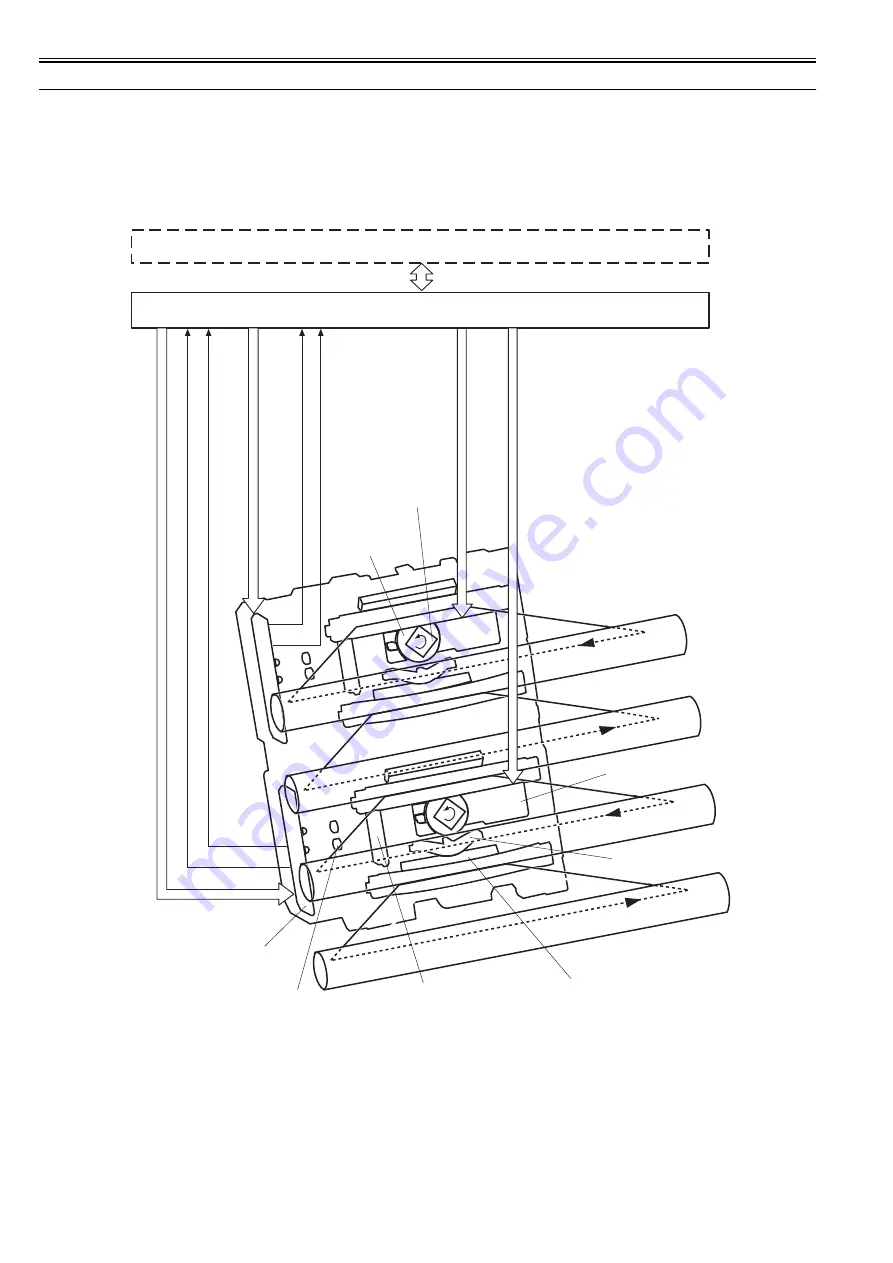
The machine's laser/scanner system serves to form latent images on the photosensitive drum according to the video signals coming from the video controller PCB,
and its principal components include the laser driver PCB and the scanner motor.
These components are grouped as a laser scanner unit, and are controlled by the DC controller PCB.
F-2-2
Video controller
/BDI34
/SCNACC12, /SCNDEC12
/BDI12
LDCTRL10, LDCTRL11, LDCTRL20, LDCTRL21
VDO1, /VDO1, VDO2, /VDO2
/SCNACC22, /SCNDEC22
LDCTRL30, LDCTRL31, LDCTRL40, LDCTRL41
VDO3, /VDO3, VDO4, /VDO4
PDOUT3, PDOUT4
PDOUT1, PDOUT2
DC Controller
Laser driver PCB
Collimator lens
Cylindrical lens
Focusing lens
Scanner mirror
(4-faceted)
Scanner motor
Scanner driver PCB
Reflecting mirror
M
C
Y
Bk
Summary of Contents for LBP5000 Series
Page 1: ...Feb 26 2007 Service Manual LBP5000 5100 Series...
Page 2: ......
Page 6: ......
Page 14: ...Contents...
Page 15: ...Chapter 1 PRODUCT DESCRIPTION...
Page 16: ......
Page 18: ......
Page 28: ......
Page 29: ...Chapter 2 TECHNICAL REFERENCE...
Page 30: ......
Page 33: ...Contents 2 8 3 2 Overview of the Block 2 39...
Page 34: ......
Page 74: ...Chapter 2 2 40 IC12 Logic IC Converts voltage levels Notation Name Description...
Page 75: ...Chapter 3 DISASSEMBLY AND ASSEMBLY...
Page 76: ......
Page 80: ......
Page 122: ......
Page 123: ...Chapter 4 MAINTENANCE AND INSPECTION...
Page 124: ......
Page 126: ......
Page 132: ......
Page 133: ...Chapter 5 TROUBLESHOOTING...
Page 134: ......
Page 136: ......
Page 141: ...Chapter 5 5 5 F 5 9...
Page 142: ...Chapter 5 5 6 F 5 10...
Page 149: ...Chapter 6 APPENDIX...
Page 150: ......
Page 152: ......
Page 161: ...Feb 26 2007...
Page 162: ......


