Chapter 2
2-4
4) The scanner mirror reflects the laser beam while rotating at a specific speed so that the beam scans the surface of the photosensitive drum at a corresponding speed.
5) When the photosensitive drum rotates at a specific speed and, in addition, the laser beam scans the surface of the photosensitive drum at a corresponding speed,
a latent image appears on the drum surface.
Note
1. Only one /BDI signal is generated to a scanner motor in this machine.
The /BDI signal to the scanner motor for M/C is generated by the reflection light from M laser, while the BDI signal to the scanner motor for Y/Bk is generated by
the reflection light from Y laser. Based on the /BDI signal, the DC controller PCB generates BD signals for four colors and send them to the video controller
PCB.
2. The machine uses a mechanism in which a single scanner mirror is used for 2 colors; in other words, the direction of scanning differs between colors. (In respect
of the printed side of a print, M/Y starts at the right edge, while C/Bk starts at the left edge.)
2.3.2 Laser Control
2.3.2.1 Outline
0010-6046
LBP5000 / LBP5100
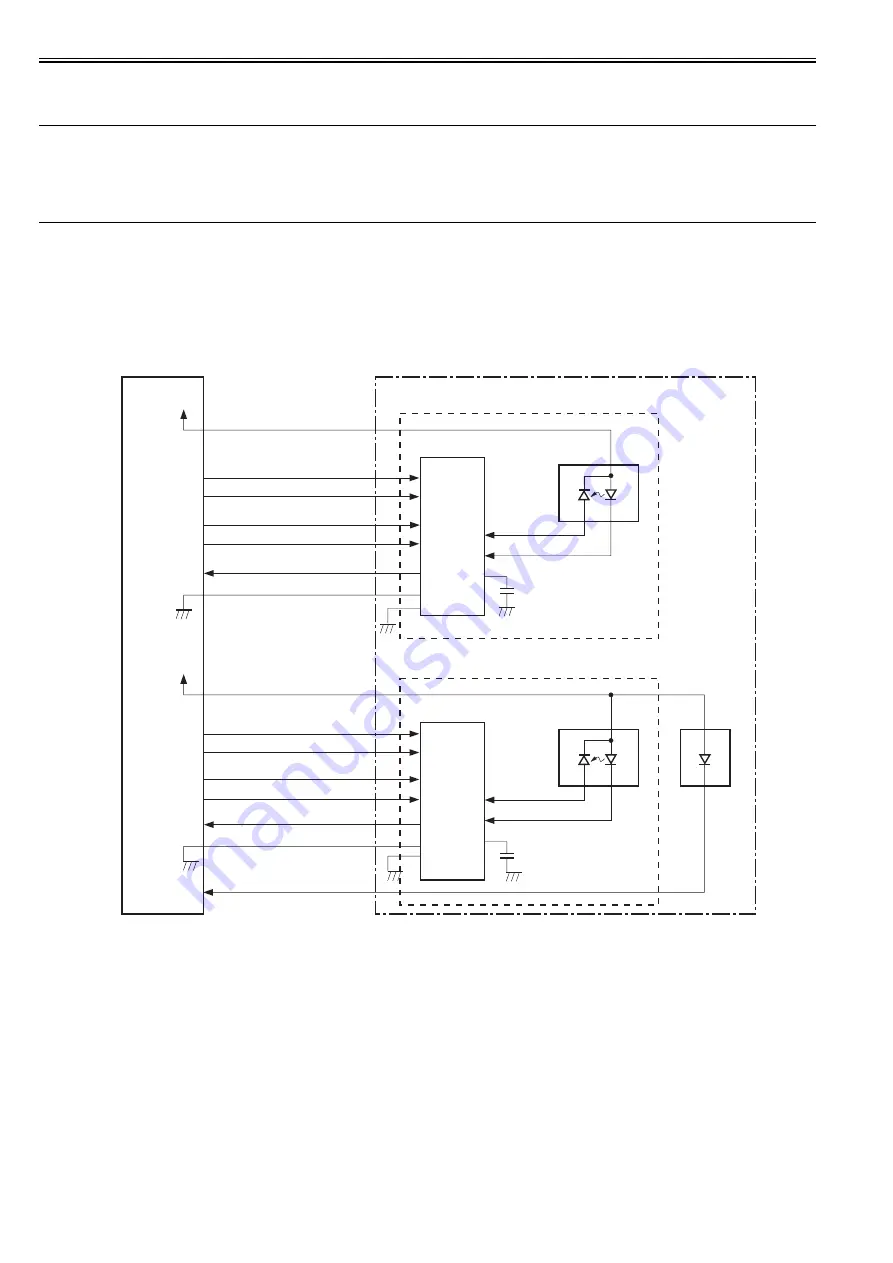
The machine's laser control consists in turning on and off the laser diode by the laser driver according to the laser control signal from the DC controller.
The machine's laser drive PCB is either for M/C or for Y/Bk; both PCBs are identical, and here, the descriptions are of the control mechanism associated with M/C.
F-2-5
The DC controller sends video signals (VDO, /VDO, used to form images) and laser control signals (LDCTRL0, LDCTRL1, used to switch the operating mode of
the laser driver circuit) to individual laser driver ICs, which control the laser activation based on the combination of laser control signals.
The machine controls its laser activation in the following 4 modes as dictated by the laser control signals:
1. laser activation control (turns on or off the laser diode according to the video signal)
2. auto photo current control (APC; makes sure that the intensity of the laser diode is at a specific level)
3. horizontal sync control (makes sure that the laser write start point in image horizontal direction is correct)
4. image mask control (makes sure that the laser beam will not be turned on in the non-image area outside the unblocking period)
The laser current output signal (PDOUT) is an analog signal that is the result of conversion of laser light into a corresponding level of current. The DC controller
PCB sends the respective intensity information to the video controller, representing individual colors (laser beams), obtained from the PDOUT signal so that the
video controller PCB may execute PWM adjustment to suit the selected gradation.
2.3.2.2 Laser Emission Control
0011-1370
LBP5000 / LBP5100
The machine turns on and off the laser diode (LD) according to video signals.
When the DC controller PCB switches the operating mode of the laser driver circuit to print mode, the machine turns on and off the laser diode (LD) at a specific
intensity as dictated by the video signal (VDO, /VDO) coming from the video control.
DC controller PCB
Laser
driver
IC
VDO1
/VDO1
C107
J401A
-3
-3
-10
-9
-12
-11
-10
-9
-12
-11
LD
PD
BD
circuit
PD
LD
IC101
PDOUT1
/BDI12
Laser driver PCB
-13
-13
-15
-15
Magenta laser driver circuit
LD101
Laser
driver
IC
C115
LD
PD
PD
LD
IC102
Cyan laser driver circuit
LD102
VDO2
/VDO2
J401A
-1
-1
-5
-4
-7
-6
-5
-4
-7
-6
PDOUT2
-14
-14
GND
-2
-2
LDCTRL20
LDCTRL21
LDCTRL10
LDCTRL11
GND
-8
-8
+5V
J112
+5V
J112
Summary of Contents for LBP5000 Series
Page 1: ...Feb 26 2007 Service Manual LBP5000 5100 Series...
Page 2: ......
Page 6: ......
Page 14: ...Contents...
Page 15: ...Chapter 1 PRODUCT DESCRIPTION...
Page 16: ......
Page 18: ......
Page 28: ......
Page 29: ...Chapter 2 TECHNICAL REFERENCE...
Page 30: ......
Page 33: ...Contents 2 8 3 2 Overview of the Block 2 39...
Page 34: ......
Page 74: ...Chapter 2 2 40 IC12 Logic IC Converts voltage levels Notation Name Description...
Page 75: ...Chapter 3 DISASSEMBLY AND ASSEMBLY...
Page 76: ......
Page 80: ......
Page 122: ......
Page 123: ...Chapter 4 MAINTENANCE AND INSPECTION...
Page 124: ......
Page 126: ......
Page 132: ......
Page 133: ...Chapter 5 TROUBLESHOOTING...
Page 134: ......
Page 136: ......
Page 141: ...Chapter 5 5 5 F 5 9...
Page 142: ...Chapter 5 5 6 F 5 10...
Page 149: ...Chapter 6 APPENDIX...
Page 150: ......
Page 152: ......
Page 161: ...Feb 26 2007...
Page 162: ......


