Chapter 2
2-39
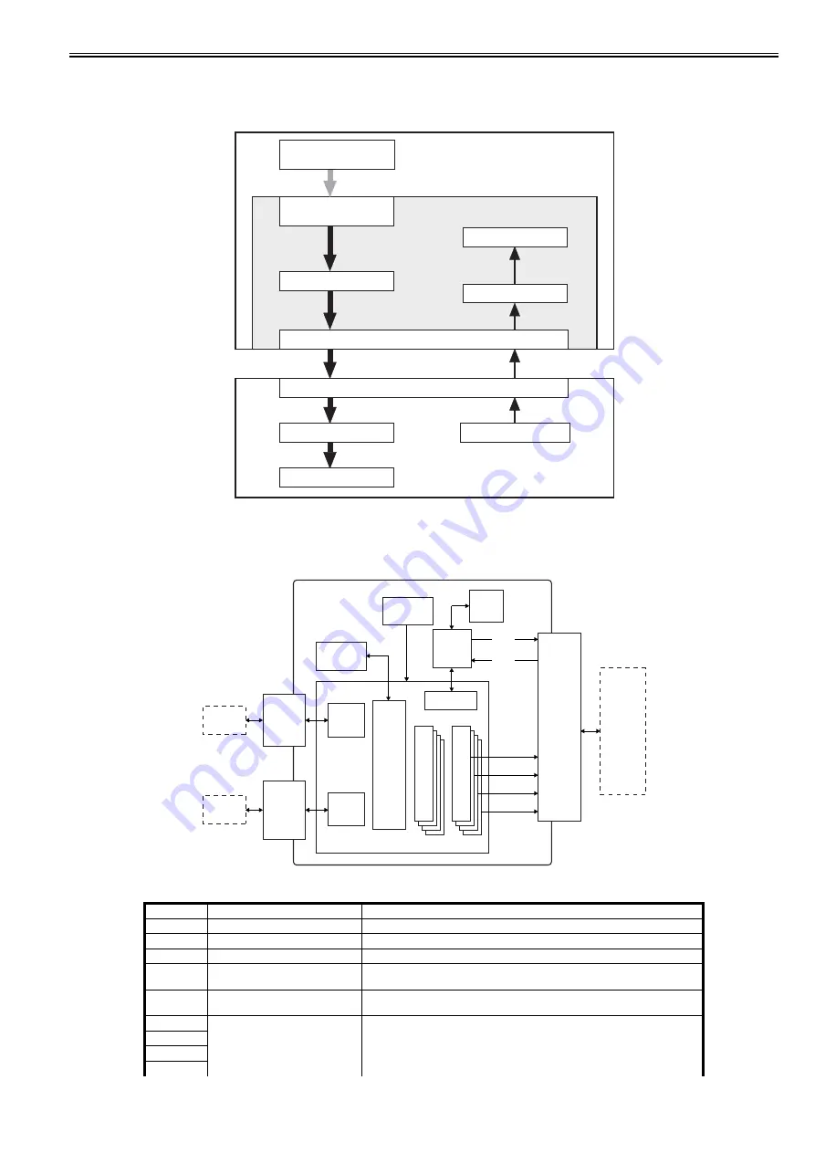
When printing is executed in a Microsoft Windows or Macintosh environment, CAPT (Canon Advanced Printing Technology) serves to reduce processing speed
and enhance the ease of operation to provide a user-friendly printing environment. To that end, CPU is designed for the following:
- The print data from the application is turned into dot data and sent to the printer without conversion into the printer's page description language (PDL).
- The printing environment may be checked and set on the host computer display by responding to dialog boxes.
- The printer status is indicated on the host computer screen: print end time, print paper movement, error status.
F-2-41
2.8.3.2 Overview of the Block
0011-0754
LBP5000 / LBP5100
F-2-42
T-2-11
Notation
Name
Description
IC1
SDRAM
Retains image data.
IC3
CPU
Controls the board.
IC5
Reset IC
Resets the board.
IC6
SSCG
Performs clock modulation. Generates modulation clock signals used by the system
clock.
IC7
ASIC
Serves as an IC for USB device controller, memory controller, video controller, and NIC
interface controller.
IC8
PWM
Converts image data from the ASIC into data by pulse width modulation.
IC9
IC10
IC11
Monitors state of printer
Creates bitmap image
Converts data into GDI-
compatible resource data
GDI data from application
Displays on screen
Host computer interface
Canon Advanced Printing Technology
Printer interface
Engine
Printing
Printer status information
Host computer
Printer
8MB
SDRAM
(IC1)
CPU I/F
CPU
(IC3)
ASIC (IC7)
MEMC
DDI-L
Connector
DC
controller
PCB
USB2.0
CORE
1Kbit
EEPROM
(ICS1)
USB
Connector
(4pin)
NIC I/F
Connector
(44pinTall)
NICC
Ella NIC
External
device
S
L
I
M
S
H
I
P
Control
system
Control
system
Video (K)
Video (C)
Video (Y)
Video (M)
J702
J704
J705
Reset IC
(IC5)
Summary of Contents for LBP5000 Series
Page 1: ...Feb 26 2007 Service Manual LBP5000 5100 Series...
Page 2: ......
Page 6: ......
Page 14: ...Contents...
Page 15: ...Chapter 1 PRODUCT DESCRIPTION...
Page 16: ......
Page 18: ......
Page 28: ......
Page 29: ...Chapter 2 TECHNICAL REFERENCE...
Page 30: ......
Page 33: ...Contents 2 8 3 2 Overview of the Block 2 39...
Page 34: ......
Page 74: ...Chapter 2 2 40 IC12 Logic IC Converts voltage levels Notation Name Description...
Page 75: ...Chapter 3 DISASSEMBLY AND ASSEMBLY...
Page 76: ......
Page 80: ......
Page 122: ......
Page 123: ...Chapter 4 MAINTENANCE AND INSPECTION...
Page 124: ......
Page 126: ......
Page 132: ......
Page 133: ...Chapter 5 TROUBLESHOOTING...
Page 134: ......
Page 136: ......
Page 141: ...Chapter 5 5 5 F 5 9...
Page 142: ...Chapter 5 5 6 F 5 10...
Page 149: ...Chapter 6 APPENDIX...
Page 150: ......
Page 152: ......
Page 161: ...Feb 26 2007...
Page 162: ......


