Chapter 2
2-14
F-2-18
2.4.1.8 Overview
0025-1150
LBP6000 / LBP6000B
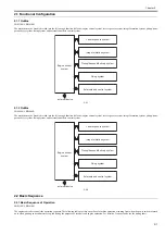
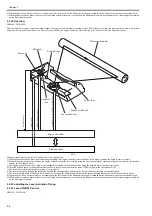
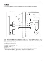
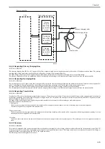
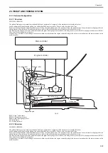
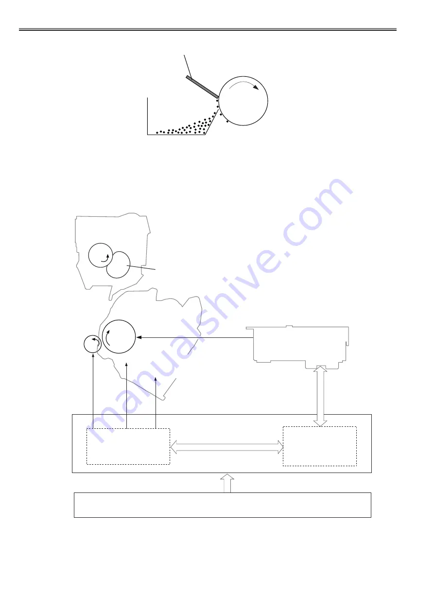
The image formation system is the core of this equipment; it forms toner images on papers.
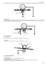
The image formation system is comprised of the following components.
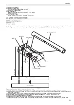
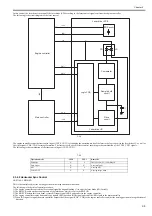
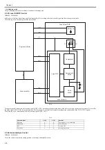
The engine controller controls the laser scanner unit and high-voltage power supply circuit and forms images based on the video signals on papers.
The following are the details of print process for this equipment and the functions of image formation.
F-2-19
2.4.1.9 Print Process
0025-1153
LBP6000 / LBP6000B
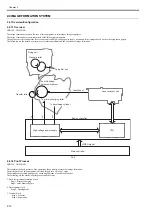
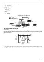
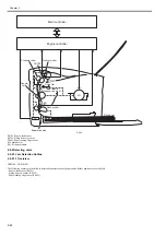
This explains the basic process of the operations that a printer executes for image formation.
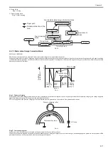
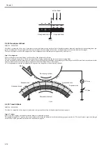
The print process of this equipment is divided largely into 5 blocks, 7 steps.
Toner images are formed on papers by executing the steps of each block in order.
Cleaning blade
Photosencitive
drum
Cleaner container
Fixing unit
Toner Cartridge
Photosensitive drum
To primary charging roller
To developing cylinder
Engine controller
TR
PRI
DEV
High-voltage power supply
VIDEO signal
Main controller
CPU
Laser scanner unit
Laser beam
Fixing film unit
Pressure roller
Transfer roller
Summary of Contents for LBP6000 Series
Page 1: ...Sep 8 2010 Service Manual LBP6000 6018 3010 3100 3150 Series...
Page 2: ......
Page 6: ......
Page 12: ...Contents...
Page 13: ...Chapter 1 PRODUCT DESCRIPTION...
Page 14: ......
Page 16: ......
Page 28: ......
Page 29: ...Chapter 2 TECHNICAL REFERENCE...
Page 30: ......
Page 74: ......
Page 75: ...Chapter 3 DISASSEMBLY AND ASSEMBLY...
Page 76: ......
Page 119: ...Chapter 4 MAINTENANCE AND INSPECTION...
Page 120: ......
Page 122: ......
Page 126: ......
Page 127: ...Chapter 5 TROUBLESHOOTING...
Page 128: ......
Page 130: ......
Page 137: ...Chapter 6 APPENDIX...
Page 138: ......
Page 140: ......
Page 144: ......
Page 145: ...Sep 8 2010...
Page 146: ......

