Chapter 2
2-39
2.8.2.2 Protective Functions
2.8.2.2.1 Protective Function of Fixing Unit
0019-7674
LBP3100 / LBP3010B
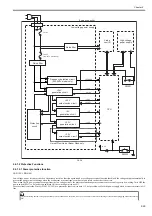
Host machine carries the following 3 functions to prevent the fixing heater from overheating.
- Protective function by CPU
- Protection function by fixing heater safety circuit
- Protection function by temperature fuse
Each function is described as below.
1) Protective function by CPU
CPU of engine controller monitors the thermistor (TH1) temperature consistently.
When TH1 reaches approx 230 deg C, CPU determines that the fixing heater is overheating and stops the fixing heater drive signal(FSRD) output and also turns
OFF relays to shut the power supply to fixing heater.
2) Protection function by fixing heater safety circuit
Fixing heater safety circuit monitors the thermistor (TH1) temperature consistently.
When TH1 reaches approx 235 deg C, it determines that the fixing heater is overheating and the fixing heater safety circuit turns OFF the relay drive circuit to
shut the power supply to the fixing heater.
3) Protection function by temperature fuse (TP1)
When the fixing heater temperature rises abnormally and temperature fuse (TP1) temperature reaches approx 226 deg C, TP1 opens to shut the power supply to
the fixing heater.
2.8.2.2.2 Error detection
0019-7678
LBP3100 / LBP3010B
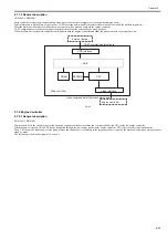
CPU of engine controller determines the fixing assembly error and shuts the fixing heater drive signal (FSRD) and also turns OFF relays to shut the power supply
to the fixing heater in the following cases. Also, it notifies the error status to the main controller simultaneously.
1) Startup error detection
- When thermistor temperature does not reach 35 deg C within 1.5 sec from heater ON.
- When the thermistor detects the temperature of 100 deg C or below during stand-by.
2) Abnormal low temperature error
- After heater ON, when the thermistor detects the temperature of 100 deg C or below at printing after the thermistor temperature reaches 50 deg C.
- After heater ON, when the thermistor detects the temperature of 55 deg C or below at sheet interval or in cleaning mode after thermistor temperature reaches
50 deg C.
3) Overheat error
When the thermistor detects the temperature of 220 deg C or over 30 times consecutively.
4) Frequency detection circuit error (200-240V series only)
When it cannot detect the frequency detection signal at fixing drive circuit even once within 3.3 sec after power ON.
2.8.2.2.3 Protective Function of Fixing Unit
0025-1178
LBP6000 / LBP6000B
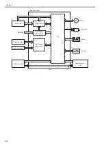
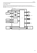
Host machine carries the following 3 functions to prevent the fixing heater from overheating.
- Protective function by CPU
- Protection function by fixing heater safety circuit
- Protection function by temperature fuse
Each function is described as below.
1) Protective function by CPU
CPU of engine controller monitors the thermistor (TH1) temperature consistently.
When TH1 reaches approx 220 deg C, CPU determines that the fixing heater is overheating and stops the fixing heater drive signal(FSRD) output and also turns
OFF relays to shut the power supply to fixing heater.
2) Protection function by fixing heater safety circuit
Fixing heater safety circuit monitors the thermistor (TH1) temperature consistently.
When TH1 reaches approx 235 deg C, it determines that the fixing heater is overheating and the fixing heater safety circuit turns OFF the relay drive circuit to
shut the power supply to the fixing heater.
3) Protection function by temperature fuse (TP1)
When the fixing heater temperature rises abnormally and temperature fuse (TP1) temperature reaches approx 226 deg C, TP1 opens to shut the power supply to
the fixing heater.
2.8.2.2.4 Error detection
0025-1179
LBP6000 / LBP6000B
Resolution Settings
This machine has 2 types of resolution settings (600 x 600 dpi, 600 x 400dpi).
This setting can be changed by whether or not ticking the item on finish settings (Finishing > Process Option > Use output adjustment mode).
600 x 400dpi is specified as factory settings. Ticking this box changes it to 600 x 600dpi.
Summary of Contents for LBP6000 Series
Page 1: ...Sep 8 2010 Service Manual LBP6000 6018 3010 3100 3150 Series...
Page 2: ......
Page 6: ......
Page 12: ...Contents...
Page 13: ...Chapter 1 PRODUCT DESCRIPTION...
Page 14: ......
Page 16: ......
Page 28: ......
Page 29: ...Chapter 2 TECHNICAL REFERENCE...
Page 30: ......
Page 74: ......
Page 75: ...Chapter 3 DISASSEMBLY AND ASSEMBLY...
Page 76: ......
Page 119: ...Chapter 4 MAINTENANCE AND INSPECTION...
Page 120: ......
Page 122: ......
Page 126: ......
Page 127: ...Chapter 5 TROUBLESHOOTING...
Page 128: ......
Page 130: ......
Page 137: ...Chapter 6 APPENDIX...
Page 138: ......
Page 140: ......
Page 144: ......
Page 145: ...Sep 8 2010...
Page 146: ......

