Chapter 3
3-4
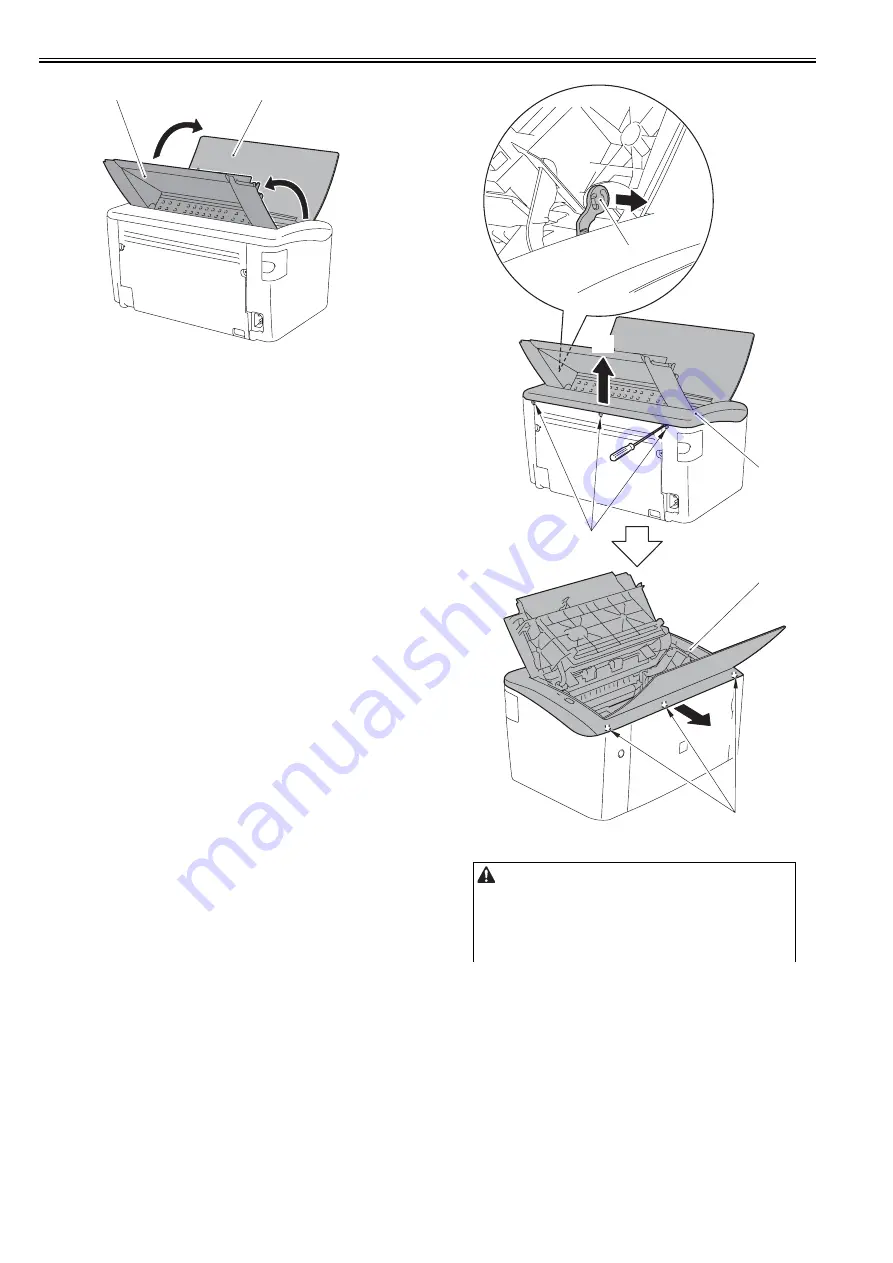
F-3-7
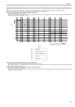
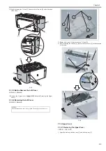
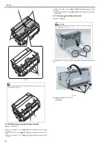
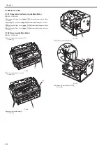
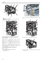
2) Remove the cartridge arm [1].
3) Release the 3 claws [3] on the upper cover [2] in the arrow [A] direction.
4) While releasing the 3 claws [4], remove the upper cover in the arrow [B]
direction.
F-3-8
[2]
[1]
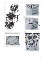
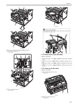
Points to note at installation
- Attach the left and right fixing pressure arms [2] to the left and right holes
[1] of the delivery tray.
- Attach the cartridge lock arm [4] to the arm unit [3] on the delivery tray.
[1]
[A]
[B]
[2]
[2]
[4]
[3]
Summary of Contents for LBP6000 Series
Page 1: ...Sep 8 2010 Service Manual LBP6000 6018 3010 3100 3150 Series...
Page 2: ......
Page 6: ......
Page 12: ...Contents...
Page 13: ...Chapter 1 PRODUCT DESCRIPTION...
Page 14: ......
Page 16: ......
Page 28: ......
Page 29: ...Chapter 2 TECHNICAL REFERENCE...
Page 30: ......
Page 74: ......
Page 75: ...Chapter 3 DISASSEMBLY AND ASSEMBLY...
Page 76: ......
Page 119: ...Chapter 4 MAINTENANCE AND INSPECTION...
Page 120: ......
Page 122: ......
Page 126: ......
Page 127: ...Chapter 5 TROUBLESHOOTING...
Page 128: ......
Page 130: ......
Page 137: ...Chapter 6 APPENDIX...
Page 138: ......
Page 140: ......
Page 144: ......
Page 145: ...Sep 8 2010...
Page 146: ......


