Chapter 2
2-11
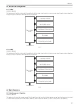
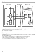
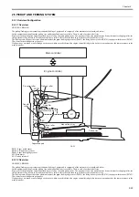
4. Fixing block
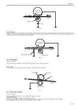
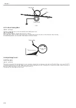
Step 6: Fixing
5. Drum cleaning block
Step 7: Drum cleaning
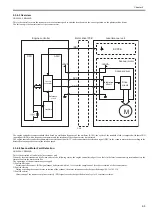
F-2-10
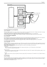
2.4.1.3 Static Latent Image Formation Block
0019-5404
LBP3100 / LBP3010B
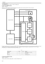
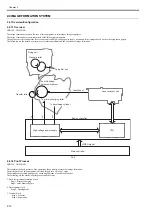
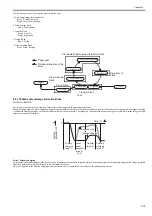
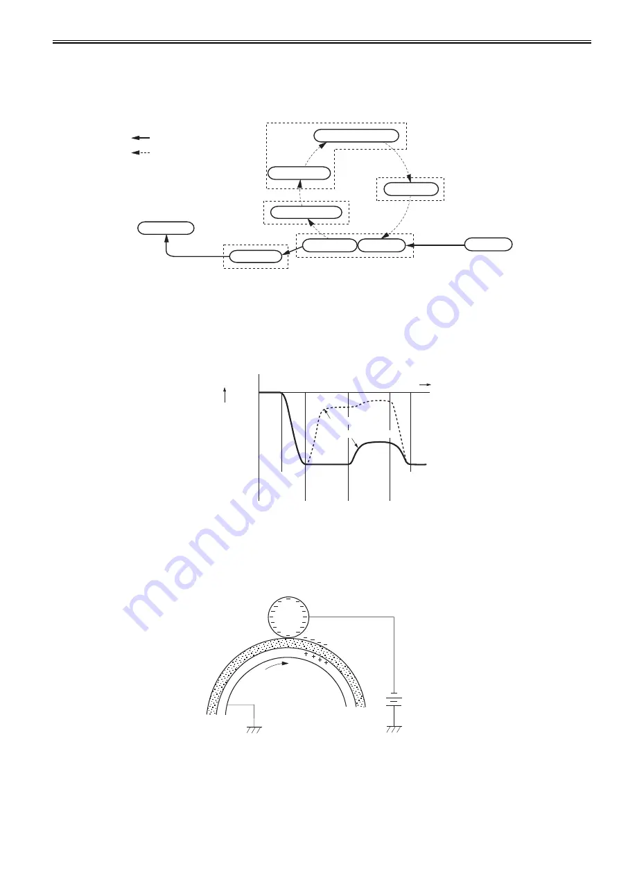
This block is comprised of two steps and forms static latent images on the photosensitive drum.
When the final step of this block completes, negative charge remains at dark areas on the drum surface where laser beam has not been exposed, and negative charge
is eliminated from bright areas on the drum surface with laser beam exposed. The images on the drum with negative charge are called static latent images because
human eyes cannot detect them.
F-2-11
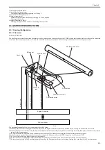
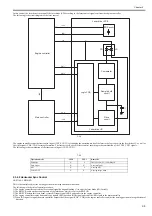
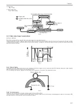
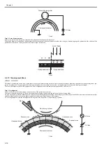
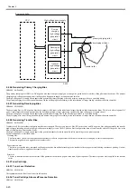
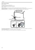
Step 1: Primary charging
For preparation of latent image formation, the surface of photosensitive drum is charged with even negative potential. In this primary charging, the charge is applied
from the primary charging roller directly to the photosensitive drum.
DC bias is applied to the primary charging roller to maintain an even potential on the surface of the photosensitive drum.
F-2-12
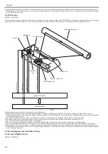
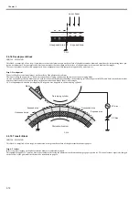
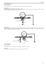
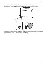
Step 2: Laser beam exposure
In this step, static latent images are formed on the photosensitive drum with laser beam.
When laser beams are scanned on the photosensitive drum negatively charged, bright areas lose their charges, eliminating negative potential on the surface of the
photosensitive drum; on those portions, static latent images are formed.
Drum cleaning
block
Transfer block
Electrostatic latent image formation block
Develoment
block
2. Laser beam exposure
Fixing block
6. Fixing
Delivery
5. Separation
4. Transfer
7. Drum cleaning
3. Development
1. Primary charging
Paper path
Rotational direction of the
drum
Pick-up
0
Time (t)
Surface
potential (V)
Laser
beam
exposure
(step 2)
Transfer
(step 4)
Primary
charging
(step 1)
Primary
charging
(step 1)
Exposed area
Unexposed area
Primary charging roller
Photosensitive drum
DC bias
Summary of Contents for LBP6000 Series
Page 1: ...Sep 8 2010 Service Manual LBP6000 6018 3010 3100 3150 Series...
Page 2: ......
Page 6: ......
Page 12: ...Contents...
Page 13: ...Chapter 1 PRODUCT DESCRIPTION...
Page 14: ......
Page 16: ......
Page 28: ......
Page 29: ...Chapter 2 TECHNICAL REFERENCE...
Page 30: ......
Page 74: ......
Page 75: ...Chapter 3 DISASSEMBLY AND ASSEMBLY...
Page 76: ......
Page 119: ...Chapter 4 MAINTENANCE AND INSPECTION...
Page 120: ......
Page 122: ......
Page 126: ......
Page 127: ...Chapter 5 TROUBLESHOOTING...
Page 128: ......
Page 130: ......
Page 137: ...Chapter 6 APPENDIX...
Page 138: ......
Page 140: ......
Page 144: ......
Page 145: ...Sep 8 2010...
Page 146: ......

