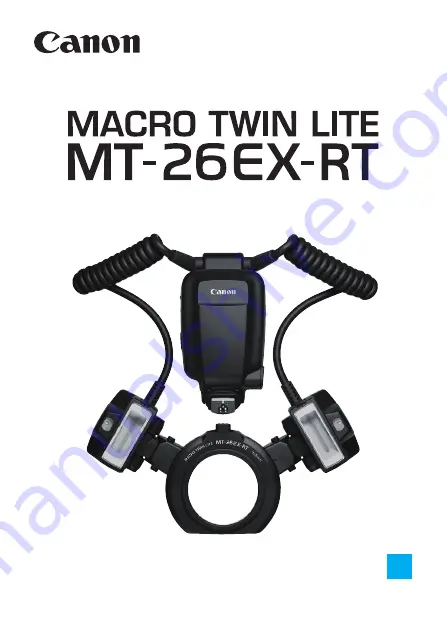
background image

E

INSTRUCTION

MANUAL

Summary of Contents for Macro Twin Light MT-26EX-RT

Page 1: ...E INSTRUCTION MANUAL...

Page 2: ...his Instruction Manual while also Referring to Your Camera s Instruction Manual Before using the product read this Instruction Manual and your camera s Instruction Manual to familiarize yourself with...

Page 3: ...amera s menu screen 51 Radio Transmission Wireless Multiple Flash Photography Wireless multiple flash shooting by radio transmission 57 Optical Transmission Wireless Multiple Flash Photography Wireles...

Page 4: ...tached to the camera and that both are turned on The icons used for buttons dials and symbols in the text match the icons found on the MT 26EX RT and the camera The selection operation performed when...

Page 5: ...the Lens 21 Adjusting the Flash Unit 22 Turning on the Power 27 a Fully Automatic Flash Photography 30 E TTL II E TTL Autoflash by Shooting Mode 32 Effective Flash Metering Range 35 D Combined Use wit...

Page 6: ...graphy 81 Optical Transmission Wireless Multiple Flash Photography 82 Optical Transmission Wireless Settings 85 a Multiple Flash Photography with Slave C Added 88 a Advanced Multiple Flash Photography...

Page 7: ...deling flash p 34 Diffuser adapter p 36 Flash exposure compensation p 40 FEB p 41 FE lock p 42 High speed sync p 43 Second curtain sync p 44 Clearing settings Reverting to defaults p 49 Flash function...

Page 8: ...ck explosion or fire Observe the following instructions when using commercially available batteries or provided battery packs Use batteries battery packs only with their specified product Do not heat...

Page 9: ...al shock and burns CAUTION Denotes the risk of injury Do not fire the flash near the eyes It may hurt the eyes Flash emits high temperatures when fired Keep fingers any other part of your body and obj...

Page 10: ...Vertical angle p 22 Flash head mount p 21 22 Flash head B p 21 36 Rotate button p 22 Focusing lamp p 33 Connecting cord Flash Unit Flash Unit Rear Flash Head Side Bottom Release levers Diffuser adapte...

Page 11: ...Dial 8 Setting button Contacts Battery compartment cover p 18 Battery compartment cover lock release lever p 18 Mounting foot locking pin External power source terminal Mounting foot Control unit p 20...

Page 12: ...d to A B f Flash exposure compensation p 40 55 Flash exposure compensation amount Firing group l Fire A B flash ratio control 4 Fire A single side firing 5 Fire B single side firing Personal Functions...

Page 13: ...tio Flash ratio control Flash mode a E TTL II E TTL autoflash q Manual flash Group flash g Wireless shooting master Firing group l Fire A B flash ratio control 4 Fire A 5 Fire B 6 Fire C slave C j Fir...

Page 14: ...81 Flash mode a E TTL II E TTL autoflash q Manual flash G Charge indicator M Master setting Transmission channel Optical transmission wireless shooting g Wirelessshooting master Firing group l Fire A...

Page 15: ...15 Nomenclature Provided Accessories Case Diffuser adapter pockets Diffuser adapter SDA E1 p 36 Flash head pockets Mount ring pocket...

Page 16: ...16...

Page 17: ...ast 10 min If you fire the flash continuously 48 times and then fire the flash again repeatedly at short intervals the safety function may activate and restrict flash firing With flash firing restrict...

Page 18: ...e This is convenient when replacing the batteries in a dark place 3 Close the cover Close the battery compartment cover and slide it up X When it clicks in place the battery compartment cover is locke...

Page 19: ...th the same area of skin for extended periods of time during use This may result in low temperature contact burns including skin redness and blistering even if the product does not feel hot The use of...

Page 20: ...oot lock lever to the right X When the lock lever clicks in place it is locked 3 Detach the control unit While pressing the lock release button slide the lock lever to the left and detach the control...

Page 21: ...or batteries immediately after continuous flash firing or modeling flash p 34 Touching them may result in a burn Make sure that the flash unit has cooled before detaching the flash unit or replacing...

Page 22: ...ad in the direction of directly move the flash head Adjusting the Flash Unit Flash Unit Adjustment Range Rotate button Standard position index Vertical angle Standard position index Horizontal angle A...

Page 23: ...fications in the table below indicate the inner angle relative to the flash head s standard position index horizontal Adjustment Guidelines Lens Magnification Flash Head Inner Angle 60 45 30 15 0 EF50...

Page 24: ...r size of the subject Also the light from the focusing lamp may be obstructed Lens Magnification Flash Head Inner Angle 60 45 30 15 0 EF180mm f 3 5L Macro USM 1 1 1 1 2 1 1 5 1 2 1 10 EF S35mm f 2 8 M...

Page 25: ...nt of the lens before attaching Macrolite Adapter p 21 to the front part of the filter If attachment threads are not provided on the front rim of the filter the flash unit cannot be attached since Mac...

Page 26: ...f 2 8 Macro IS STM first attach the hood then attach the mount ring If a hood is attached a 58 mm filter cannot be attached to the filter mounting thread of the mount ring With the EF100mm f 2 8 Macro...

Page 27: ...s available regardless of the camera s drive mode setting Although the flash output will be approx 1 2 to 1 6 of the full output it is useful for shooting with a shorter firing interval During manual...

Page 28: ...iple flash shooting p 58 the time until auto power off takes effect is approx 5 min By setting the power switch to a you can disable the flash s button and dial operations It is useful when you want t...

Page 29: ...ower is turned off To retain the settings when replacing the batteries replace the batteries after turning off the power switch You can fire a test flash or turn on off the focusing lamp while the pow...

Page 30: ...us on the subject Press the shutter button halfway to focus X The shutter speed and aperture are displayed in the viewfinder Check that Q is lit in the viewfinder 3 Take the picture When you press the...

Page 31: ...dark underexposed when you check the shot image move closer to the subject and shoot again You can also increase the ISO speed when using a digital camera Fully automatic refers to A 1 and C shooting...

Page 32: ...ased on the metering of the camera For low light scenes a slow sync speed will be used to obtain the standard exposure for both the main subject and background The standard exposure for the main subje...

Page 33: ...amage If you shoot when the focusing lamp is lit underexposure may occur If necessary set the exposure compensation or flash exposure compensation Under conditions where the flash is not fired such as...

Page 34: ...uction Manual to find out if it is compatible with this function Modeling FlashM Color Temperature Information Transmission To avoid degrading and damaging the flash head due to overheating do not fir...

Page 35: ...35 The MT 26EX RT s effective flash metering range largely varies depending on the flash heads position Effective Flash Metering Range...

Page 36: ...a flash head until it clicks in place as shown The diffuser adapter can be attached to either flash head A or B X The display indicating that the diffuser adapter is being used is shown When removing...

Page 37: ...er adapter attached taking the picture after the flash ready lamp is lit in red is recommended since the flash output may not be sufficient If you attach the diffuser adapter to MT 26EX RT when using...

Page 38: ...e set in half stop increments as follows 8 1 to 1 1 to 1 8 13 settings 1 Set to l Press the button Turn 9 select U then press 8 2 Press the F button Press function button 3 F X The flash ratio is high...

Page 39: ...firing will apply EOS Elan II Elan II E 50 50E EOS REBEL XS N REBEL G II 3000N 66 EOS REBEL 2000 300 EOS REBEL G 500N EOS IX EOS IX Lite IX 7 The flash ratio of 8 1 to 1 1 to 1 8 is equivalent to 3 1...

Page 40: ...amount is set 0 3 indicates 1 3 stop and 0 7 indicates 2 3 stops To cancel flash exposure compensation return the compensation amount to 0 f Flash Exposure CompensationN Generally set an increased ex...

Page 41: ...en the FEB range exceeds 3 stops the end of the flash exposure level shows I or J g FEBN After the three shots are taken FEB is canceled automatically Before shooting with FEB it is recommended to set...

Page 42: ...r approx 0 5 sec Each time you press the B button a preflash will be fired and the new flash output required at that time is retained in memory FEL FE LockN If a correct exposure cannot be obtained wh...

Page 43: ...tdoors in daylight Display c Press function button 4 Y to display c Check that F is lit in the viewfinder then shoot c High speed Sync N With high speed sync the faster the shutter speed the lower the...

Page 44: ...button 4 Y to display r r Second curtain SyncN The second curtain sync works well when the camera s shooting mode is set to bulb B bulb shooting When the flash mode is set to a the flash fires twice...

Page 45: ...mode to q Press the E button Turn 9 select R then press 8 2 Turn off the display Press the button Turn 9 select M then press 8 3 Set the flash output Press function button 2 or 8 X The flash output l...

Page 46: ...head Press function button 3 F or 8 and turn 9 to select flash head A or B 3 Set the flash output Press function button 3 1 or 8 Turn 9 to set the flash output then press 8 Repeat steps 2 and 3 to set...

Page 47: ...FlashN 1 Set 4 or 5 Press the button Turn 9 select a or b then press 8 2 Set the flash output Press function button 3 or 8 Turn 9 to set the flash output then press 8 Single side Firing Fire B only F...

Page 48: ...entire spot metering circle within the viewfinder center is over the gray reflector 4 Press the B P or 7 button 8 X The MT 26EX RT will fire a preflash and the required flash output for the correct f...

Page 49: ...r seconds until w is displayed X The MT 26EX RT settings are cleared and normal flash photography with a flash mode will be set Clearing MT 26EX RT SettingsN Even when the settings have been cleared t...

Page 50: ...50...

Page 51: ...ibes how to set the flash functions from the camera s menu screen When the camera s shooting mode is set to a fully automatic mode or a Basic Zone mode the operations in this chapter are not available...

Page 52: ...Flash control 2 Select Flash function settings Select Flash function settings or External flash func setting X The setting screen is displayed 3 Set the function The setting screen and items displayed...

Page 53: ...EL T4i 650D EOS M2 EOS M On the camera s flash function setting screen you can configure the settings for normal flash photography radio transmission wireless multiple flash shooting and optical trans...

Page 54: ...depending on the scene This setting is for advanced users Flash synchronization speed in Av mode You can set the flash synchronization speed when shooting in aperture priority AE f mode with flash Fla...

Page 55: ...ing the flash output The settable range is up to 3 stops in 1 3 stop increments Wireless functions You can set radio transmission wireless multiple flash shooting and optical transmission wireless mul...

Page 56: ...ct an item and set the function To clear all the Custom Function settings select Clear settings in step 1 then Clear all Speedlite C Fn s or Clear ext flash C Fn set Flash Custom Function Settings Cus...

Page 57: ...camera s shooting mode is set to a fully automatic mode or a Basic Zone mode the operations in this chapter are not available Set the camera s shooting mode to d s f a bulb B Creative Zone mode With...

Page 58: ...ate the slave unit during shooting Multiple Flash Photography with Slave C Added p 69 You can perform multiple flash shooting using flash heads A and B of the master unit and a slave unit set to firin...

Page 59: ...and slave B to fire with flash head B as a group as a single flash unit B A C Shooting with firing group C pointed directly toward the main subject may result in overexposure Before shooting perform...

Page 60: ...main functional differences are as follows Some restrictions apply depending on the camera used See p 62 78 Difference between Radio Transmission and Optical Transmission Function Radio Transmission...

Page 61: ...to fire with flash head B as a group as a single flash unit Multiple units can be used as slave C D and E You can increase the number of slave units up to 15 units Group Control Slave C Slave D Slave...

Page 62: ...ssion wireless shooting using E TTL autoflash is not possible Shoot with manual flash p 76 or optical transmission wireless multiple flash p 81 EOS 1Ds EOS 1D EOS 1V EOS 3 EOS Elan II Elan II E 50 50E...

Page 63: ...63 Radio Transmission Wireless Multiple Flash Photography 2 High speed sync shooting is not possible 3 Group flash p 78 is not possible...

Page 64: ...t the slave firing group A B C while referring to the Instruction Manual of the Speedlite equipped with the radio transmission wireless slave function Radio Transmission Wireless Settings Master Unit...

Page 65: ...function button 4 to display O 2 Set a transmission channel Press function button 1 C Turn 9 to select AUTO or any channel between Ch 1 to 15 then press 8 3 Set a wireless radio ID Press function butt...

Page 66: ...o the scan results Scanning when AUTO is set Run the scan Press function button 4 to display O Press function button 3 W X The scan is performed and the channel with the best reception signal is reset...

Page 67: ...r and slave unit total to 16 or less Error Turn the master unit and slave unit off and on again If the transmission channels of the master unit and slave unit are different the slave unit will not fir...

Page 68: ...the settings later 1 Display L Press function button 4 to display N 2 Save or load the settings Press function button 3 L Save Press function button 1 V X The settings are saved stored in the memory...

Page 69: ...ission channel and wireless radio ID If the channels of the master unit and slave unit are different set them both to AUTO or set them to the same number p 65 If the wireless radio ID of the master un...

Page 70: ...n amount for slave C Turn 9 select h then press 8 Turn 9 to set the flash exposure compensation amount then press 8 7 Check the transmission status and charge status Check that w is not displayed on t...

Page 71: ...Check the transmission channels and wireless radio IDs of the master unit and slave unit again If you cannot connect with the same settings turn the master unit and slave unit off and on again Shooti...

Page 72: ...slave units are not fully charged When the master unit and slave units are fully charged the LCD panel illumination will turn off after approx 12 sec When the charging of the master unit and slave un...

Page 73: ...display on the LCD panel will change depending on the order in which the master setting was performed The first master main master is displayed as M and the second and subsequent masters sub masters...

Page 74: ...firing at the same output or with only slave A or B added regardless of the slave s firing group settings 1 Set l and 6 Press the button Turn 9 select W then press 8 2 Set and position slave A B and...

Page 75: ...e flash exposure compensation amount for slave C following the procedure described in Multiple Flash Photography with Slave C Added p 69 then take the picture To fire flash heads A and B and the slave...

Page 76: ...press 8 2 Set the firing group Press the button Turn 9 to select the firing method from the options below You can perform wireless multiple flash shooting with slave A B and C added All slave units ha...

Page 77: ...teps 3 and 4 to set the flash output of all groups 5 Take the picture X Each group fires at the set flash output If high speed sync is set the setting range will be 1 1 1 64 When j is set set A B or C...

Page 78: ...ho are very knowledgeable and experienced in lighting 1 Set the flash mode to Press the E button on the master unit Turn 9 to select F then press 8 The slave unit s flash mode is set automatically dur...

Page 79: ...t the firing mode from a q or Setting the flash output and flash exposure compensation amount Press function button 3 1 Turn 9 to set the flash output or flash exposure compensation amount then press...

Page 80: ...When f or g is set to f or g of the MT 26EX RT will not fire When setting the flash mode to make sure the slave units are the Speedlites supporting the Auto external flash metering Firing in this flas...

Page 81: ...or optical transmission wireless multiple flash photography see the system map p 108 When the camera s shooting mode is set to a fully automatic mode or a Basic Zone mode the operations in this chapte...

Page 82: ...ave unit during shooting Multiple Flash Photography with Slave C Added p 88 You can perform multiple flash shooting using flash heads A and B of the master unit and a slave unit set to firing group C...

Page 83: ...lash unit B A C Shooting with firing group C pointed directly toward the main subject may result in overexposure Before shooting perform a test flash p 27 and test shooting To avoid interfering with t...

Page 84: ...nd slave B to fire with flash head B as a group as a single flash unit Multiple units can also be set as slave C Note that there is no limit for the number of units that can be used as slave A B or C...

Page 85: ...then press 8 Press the button then select the firing method from the options below p 92 _ and j and l and l 6 Set the slave firing group A B C while referring to the Instruction Manual of the Speedlit...

Page 86: ...to the Instruction Manual of the Speedlite equipped with the optical transmission wireless slave function 1 Display N Press function button 4 to display N 2 Set a transmission channel Press function b...

Page 87: ...l the settings later 1 Display L Press function button 4 to display N 2 Save or load the settings Press function button 3 L Save Press function button 1 V X The settings are saved stored in the memory...

Page 88: ...Set l and 6 Press the button Turn 9 select W then press 8 3 Check the transmission channel If the channels of the master unit and slave unit are different set them to the same number p 86 4 Set slave...

Page 89: ...nt then press 8 7 Check that the flash is ready Check that the master unit s flash ready lamp is lit Check that the slave unit is fully charged 8 Check the performance Press the master unit s test fla...

Page 90: ...II E 50 50E EOS REBEL XS N REBEL G II 3000N 66 EOS REBEL 2000 300 EOS REBEL G 500N EOS IX EOS IX Lite IX 7 If there is a fluorescent light or computer monitor near a slave unit the presence of the lig...

Page 91: ...this wireless system you do not need to operate the slave unit s For this reason you can perform optical transmission wireless multiple flash photography in the same way as normal flash photography M...

Page 92: ...lave unit s firing at the same output or with only slave A or B added regardless of the slave s firing group settings 1 Set l and 6 Press the button Turn 9 select W then press 8 2 Set and position sla...

Page 93: ...e flash exposure compensation amount for slave C following the procedure described in Multiple Flash Photography with Slave C Added p 88 then take the picture To fire flash heads A and B and the slave...

Page 94: ...s 8 2 Set the firing group Press the button Turn 9 to select the firing method from the options below You can perform wireless multiple flash shooting with slave A B and C added All slave units have t...

Page 95: ...sh output then press 8 Repeat steps 3 and 4 to set the flash output of all groups 5 Take the picture X Each group fires at the set flash output If high speed sync is set the setting range will be 1 1...

Page 96: ...96...

Page 97: ...e MT 26EX RT with the Custom Functions C Fn and Personal Functions P Fn When the camera s shooting mode is set to a fully automatic mode or a Basic Zone mode the operations in this chapter are not ava...

Page 98: ...X The Custom Functions screen is displayed 2 Select an item to set Turn 9 to select an item number to be set 3 Change the setting Press 8 X The setting is displayed Turn 9 to select your desired sett...

Page 99: ...n 18 I Macro Focusing lamp on off p 103 C Fn 22 LCD panel illumination Personal Function List Number Item Page P Fn 01 K Macro Focusing lamp brightness p 104 P Fn 02 L Macro Focusing lamp on time P Fn...

Page 100: ...n all the Custom Functions that have been set are cleared Similarly when the same operations are performed on the Personal Function screen all the Personal Functions that have been set are cleared Cle...

Page 101: ...RT s test flash button to fire the modeling flash 2 Enabled with both buttons Press the camera s depth of field preview button or the MT 26EX RT s test flash button to fire the modeling flash 3 OFF D...

Page 102: ...ing both internal and external power sources 1 2 External power only You can minimize the consumption of the internal power source by using only external power source to charge for firing the flash wh...

Page 103: ...focusing lamp by pressing the d button C Fn 22 B LCD panel illumination When a button or dial is operated the LCD panel illuminates You can change this illumination setting 0 12sec On for 12 sec 1 OF...

Page 104: ...P Fn 02 L Macro Focusing lamp on time You can select the lighting time of the focusing lamp 0 20sec 20 sec 1 5min 5 min P Fn 03 LCD panel display contrast You can adjust the contrast of the LCD panel...

Page 105: ...the flash fire the Quick flash when the flash ready lamp is lit in green before the flash is fully charged to shorten the charge waiting time 0 ON Enabled 1 OFF Disabled When Quick flash p 27 is fire...

Page 106: ...106...

Page 107: ...107 6 Reference This chapter provides a system map and troubleshooting guide and describes the use of the MT 26EX RT with Type B cameras...

Page 108: ...Provided with MT 26EX RT Macrolite Adapter An adapter for attaching the flash unit to the lens p 21 MT 26EX RT System Wireless multiple flash photography Radio transmission Speedlite with slave funct...

Page 109: ...ery Pack CP E4N A small and lightweight external power source with superior portability When using a Speedlite without a function for switching the firing groups A B C in you can use the Speedlite as...

Page 110: ...8 sec level 1 or approx 20 sec level 2 As the internal temperature of the flash unit increases the warning is displayed in two levels When you perform continuous firing repeatedly even more in the sta...

Page 111: ...o heat up If level 2 warning is displayed allow a rest time for at least 25 min Even if you stop flash firing after level 1 warning is displayed level 2 warning may be displayed If flash photography i...

Page 112: ...the G indication remains displayed for approx 30 sec or longer replace the batteries p 18 If the electrical contacts of the control unit or camera are dirty wipe the contacts p 11 with a dry cloth et...

Page 113: ...e to the program AE d or fully automatic mode p 32 Note that you can also set the sync speed in Flash sync speed in Av mode p 54 Set the camera s shooting mode to d s f a bulb B Creative Zone mode Set...

Page 114: ...front side of the slave s main body toward the master unit When performing autoflash photography with three firing groups A B and C do not fire with firing group C pointing toward the main subject p 7...

Page 115: ...ssion range of the master unit p 82 Point the wireless sensor of the slave unit toward the master unit p 82 Position the slave unit at a location with the clearest possible view of the master unit If...

Page 116: ...rmal flash Approx 1 8 ms or less Quick flash Approx 2 3 ms or less Color temperature information transmission Flash light color temperature information transmitted to camera when flash is fired Filter...

Page 117: ...0 1 5 5 sec Quick flash Approx 0 1 3 3 sec When using AA LR6 alkaline batteries Flash ready lamp Lights up in red Normal flash available Lights up in green Quick flash available Radio Transmission Wi...

Page 118: ...n using AA LR6 alkaline batteries Power saving Power off after approx 90 sec of idle operation Power off after approx 5 min of idle operation during radio transmission wireless multiple flash shooting...

Page 119: ...119...

Page 120: ...36 1 1 8 9 2 30 2 7 0 23 0 1 250 12 8 42 0 9 8 32 2 1 16 6 5 21 3 5 0 16 4 1 320 11 4 37 4 8 8 28 9 1 32 4 6 15 1 3 5 11 5 1 400 10 2 33 5 7 8 25 6 1 64 3 3 10 8 2 5 8 2 1 500 9 1 29 9 7 0 23 0 1 128...

Page 121: ...m camera supporting TTL autoflash are manual flash p 45 and second curtain sync p 44 only Other functions are not available When the MT 26EX RT is attached to a Type B camera a is displayed on the LCD...

Page 122: ...9 1216 FCC ID AZD216 IC 498J 216 This device complies with Part 15 of FCC Rules and Industry Canada s license exempt RSSs Operation is subject to the following two conditions 1 this device may not cau...

Page 123: ...15 of the FCC Rules These limits are designed to provide reasonable protection against harmful interference in a residential installation This equipment generates uses and can radiate radio frequency...

Page 124: ...esignated collection point e g on an authorized one for one basis when you buy a new similar product or to an authorized collection site for recycling waste electrical and electronic equipment EEE Imp...

Page 125: ...2 External power 102 109 F FE lock FEL 42 FEB 41 55 Filter 25 Firing groups 58 61 74 76 78 82 84 92 94 Firing interval 17 18 110 Firing ratio control 55 A B 38 70 89 A B C 69 74 88 92 RATIO button 38...

Page 126: ...apter 21 108 Modeling flash 34 101 Multiple flash photography 58 82 N Nomenclature 10 Normal flash 18 120 Number of flashes 18 O Optical transmission wireless multiple flash photography 81 P P Program...

Page 127: ...ion distance 58 60 Transmission range 82 TTL autoflash 121 Tv Shutter priority AE 32 Type A camera 2 Type B camera 121 W Warning icon 62 110 Wireless multiple flash photography A B C 64 69 74 85 88 92...

Page 128: ...ns in this Instruction Manual are current as of July 2017 For information on the compatibility with any products introduced after this date contact any Canon Service Center For the latest version Inst...

Reviews: