4
4
4-70
4-70
Disassembly/Assembly > Document Exposure/Feeder System > Removing the Flatbed Motor Unit
Disassembly/Assembly > Document Exposure/Feeder System > Removing the Flatbed Motor Unit
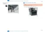
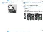
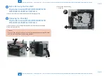
Before Removing the Flatbed Motor Unit
1-1) Remove the left cover. (Duplex models) (Refer to page 4-31)
1-2) Remove the left cover. (Single-sided models) (Refer to page 4-32)
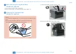
2-1) Remove the DADF unit and reader unit. (models with DADF) (Refer to page 4-40)
2-2) Remove the SADF unit and reader unit. (models with SADF) (Refer to page 4-53)
2-3) Remove the copyboard cover and reader unit. (models with copyboard) (Refer to page
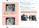
3-1) Remove the DADF unit. (models with DADF) (Refer to page 4-42)
3-2) Remove the SADF unit. (models with SADF) (Refer to page 4-55)
3-3) Remove the copyboard cover. (models with copyboard) (Refer to page 4-64)
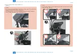
4-1) Remove the control panel unit. (models with FAX) (Refer to page 4-79)
4-2) Remove the control panel unit. (models without FAX) (Refer to page 4-79)
5-1) Remove the copyboard glass. (models with copyboard) (Refer to page 4-66)
5-2) Remove the copyboard glass. (models with DADF/models with SADF) (Refer to page
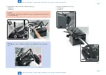
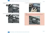
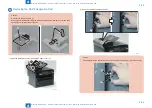
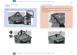
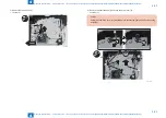
Removing the Flatbed Motor Unit
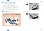
Caution:
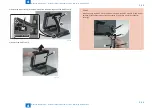
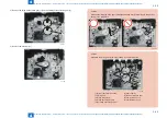
When assembling/disassembling the flatbed motor unit, take care not to lose the 2 CIS
unit spacers [1].
When assembling/disassembling the flatbed motor unit, do not touch the copy reading
area [A] of the CIS unit.
[A]
[1]
F-4-156
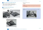
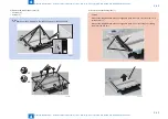
Caution:
Grease is applide on the shaft [1] of the Contact Sensor, so be careful not to let the belt
[2] come in contact with the shaft.
[1]
[2]
F-4-157
Summary of Contents for MF4500 Series
Page 222: ...5 5 Adjustment Adjustment Mechanical Adjustment ...
Page 224: ...6 6 Trouble Shooting Trouble Shooting Test Print Trouble Shooting Items Version Upgrade ...
Page 230: ...7 7 Error Codes Error Codes Overview Error Codes ...
Page 234: ...8 8 Service Mode Service Mode Overview COPIER FEEDER FAX TESTMODE ...
Page 251: ... Service Tools Solvent Oil List General Circuit Diagram General Timing Chart Appendix ...

