4
4
4-2
4-2
Disassembly/Assembly > Outline
Disassembly/Assembly > Outline
Outline
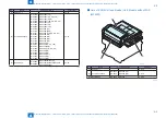
This chapter describes disassembling/assembling procedure of this equipment.
The service technician is to identify the cause of the failures according to "Chapter 5
Troubleshooting" and to replace the faulty parts by following the disassembling procedure. In
addition, replace the consumable parts by following the same disassembling procedure.
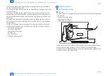
Note the following precautions when working.
1. CAUTION: Be sure to disconnect the power plug before disassembling/assembling for
safety.
2. When disassembling/assembling or transporting the machine, be sure to remove the
cartridge beforehand as needed. However, when the cartridge is removed from the
machine, be sure to put the Photosensitive Drum in a protective bag even in a short period
of time to prevent the adverse effect of light.
3. When assembling, perform the disassembling procedure in reverse order unless otherwise
specified.
4. When assembling, be sure to tighten the screws to their appropriate locations according to
the screw types (length, diameter).
5. Do not run the machine with any parts removed as a general rule.
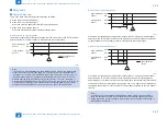
6. When handling the PCB, be sure to touch the metal part of the printer to ground yourself to
prevent damaging the PCB by static electricity.
7. When replacing the part with the rating name plate, be sure to affix it to the new part.
Summary of Contents for MF4500 Series
Page 222: ...5 5 Adjustment Adjustment Mechanical Adjustment ...
Page 224: ...6 6 Trouble Shooting Trouble Shooting Test Print Trouble Shooting Items Version Upgrade ...
Page 230: ...7 7 Error Codes Error Codes Overview Error Codes ...
Page 234: ...8 8 Service Mode Service Mode Overview COPIER FEEDER FAX TESTMODE ...
Page 251: ... Service Tools Solvent Oil List General Circuit Diagram General Timing Chart Appendix ...


