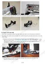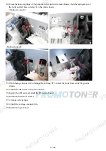
12) Hook the torsion springs of the pressure roller unit to the main chassis, then the springs kept at
the right and left plates in step 6) to the main chassis.
<Springs in step 6)>
<Springs hooked>
13) While being cautious not to damage the carriage FFC, install the front chassis and the ground
chassis.
14) Attach the ink sensor to the front chassis.
15) Install the ASF unit and attach the PE sensor board.
16) Install the main PCB chassis.
17) Arrange each harness.
18) Attach the carriage encoder film.
19) Install the logic board.
37 / 66
Summary of Contents for MG6110
Page 24: ...5 Remove the main case no screws 20 66...
Page 36: ...3 Attach the cassette feed guide 4 Install the cassette feed roller unit 32 66...
Page 44: ...4 Slowly lift the print unit to separate it from the bottom case 40 66...
Page 58: ...54 66...
Page 63: ...4 2 Integrated Inspection Pattern Print Print sample 59 66...
Page 64: ...4 3 Ink Absorber Counter Value Print Print sample 4 VERIFICATION AFTER REPAIR 60 66...
Page 68: ...64 66...


