(14/58)
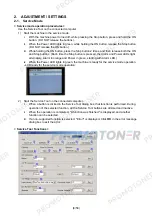
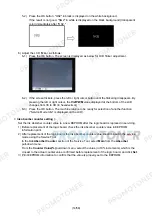
5-2) Press the OK button. "OK2" in black is displayed on the white background.
If the result is not good, "NG2" in white is displayed on the black background (transparent
color) immediately after "OK2."
6) Adjust the LCD flicker, as follows:
6-1) Press the OK button. The screen is displayed as below for LCD flicker adjustment.
6-2) If the screen flickers, press the left or right cursor button until the flickering disappears. By
pressing the left or right cursor, the
VrefPWM
value displayed at the bottom of the LCD
changes from 36 to 3D (in hexadecimal).
6-3) Press the OK button. The machine returns to be ready for selection of another function
("Service Mode Idle" is displayed on the LCD).
< Ink absorber counter setting >
Set the ink absorber counter value to a new EEPROM after the logic board is replaced in servicing.
1) Before replacement of the logic board, check the ink absorber counter value in EEPROM
information print.
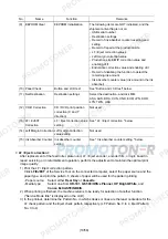
2) After replacement of the logic board, the ink absorber counter value should be set in the service
mode using the Service Tool.
In
the
Ink Absorber Counter
section of the Service Tool, select
Main
from the
Absorber
pull-down menu.
From
the
Counter Value(%)
pull-down menu, select the value (in 10% increments) which is the
closest to the actual counter value confirmed before replacement of the logic board, and click
Set
.
3) Print EEPROM information to confirm that the value is properly set to the EEPROM.
Summary of Contents for MP540
Page 11: ...11 58...
Page 19: ...19 58 7 Remove the main case and sub case 1 screw...
Page 27: ...27 58 3 EXTERNAL VIEW PARTS LIST FIGURE 1 PACKING CONTENTS PRINT HEAD...
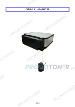
Page 29: ...29 58 FIGURE 2 AC ADAPTER...
Page 31: ...31 58 FIGURE 3 EXTERNAL COVERS SCANNER UNIT...
Page 33: ...33 58 FIGURE 4 DOCUMENT PRESSURE PLATE UNIT...
Page 35: ...35 58 FIGURE 5 OPERATION PANEL UNIT...
Page 37: ...37 58 FIGURE 6 MAIN CASE FRONT DOOR UNIT...
Page 39: ...39 58 FIGURE 7 BOTTOM CASE INK ABSORBER...
Page 41: ...41 58 FIGURE 8 LOGIC BOARD ASS Y PE SENSOR BOARD ASS Y...
Page 43: ...43 58 FIGURE 9 SHEET FEED UNIT...
Page 45: ...45 58 FIGURE 10 CARRIAGE UNIT PRESSURE ROLLER UNIT...
Page 47: ...47 58 FIGURE 11 PLATEN UNIT SPUR UNIT...
Page 49: ...49 58 FIGURE 12 PURGE DRIVE SYSTEM UNIT SWITCH SYSTEM UNIT...
Page 51: ...51 58 FIGURE 13 OPTION CONSUMABLES...
Page 53: ...53 58 FIGURE 14 TOOL...
Page 55: ...55 58 REFERENCE PRINTER UNIT...


