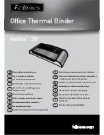


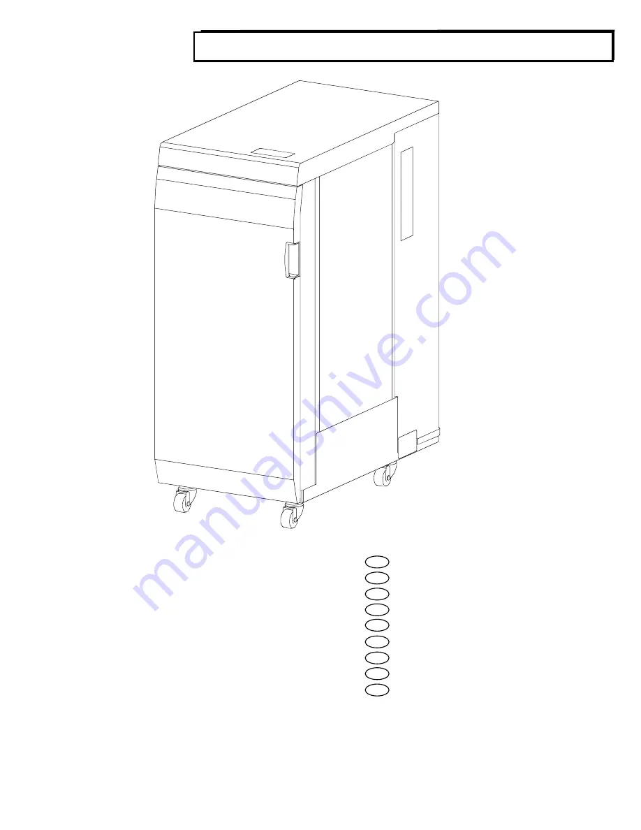
Multi Function Professional Puncher
– B1
EN
Operation Instructions Manual
F
Manuel d'instructions et d'utilisation
E
Manual de instrucciones de operación
I
Manuale d’istruzioni
D
Bedienungsanleitung
NL
Gebruiksaanwijzing
PT
Manual de instruções de operação
RU
Руководство по эксплуатации
CHI
操作使用手册
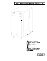
Part Number: 7723867
Revision number: E1
Issue Date: May 2020