background image

No. D17-8116

Digital Video Camera

CANON INC. 2004

Canon Inc.

Digital Imaging Products Service Dept.

First Edition : Jan. 2004

First Print : Jan. 2004

iPAL

Video Product

c

MV750i E, MV730i E

MV700i E, MV700 E 

MV690 E

MV750i E, MV730i E

MV700i E, MV700 E 

MV690 E

Summary of Contents for MV750i E

Page 1: ...deo Camera CANON INC 2004 Canon Inc Digital Imaging Products Service Dept First Edition Jan 2004 First Print Jan 2004 iPAL Video Product c MV750i E MV730i E MV700i E MV700 E MV690 E MV750i E MV730i E MV700i E MV700 E MV690 E ...

Page 2: ... 2 2 New technologies and new functions 12 2 3 Skin detail mode 13 2 3 1 Design objectives of skin detail image quality setting 13 2 4 End search 14 3 Performance 16 4 System Diagram Common to all Models 28 5 Overview of viewfinder LCD panel displays 29 5 1 Camera mode 29 5 2 VCR mode 36 5 3 Card Camera mode MV750i E MV730i E only 40 5 4 Card Playback mode MV750i E MV730i E only 42 5 4 1 Still ima...

Page 3: ...splays Motion JPEG 1 2 Main Features 1 Compact Stylish New Stylish Design 2 High Performance Lens 22 optical zoom lens compatible with 1 6 inch CCD MV750i E only 3 Excellent Picture Quality DIGIC DV system used 4 Multimedia Motion JPEG Camera Direct MV750i E MV730i E only 5 Advanced Specification New Digital Feature 6 All In One 2 5 inch LCD and CVF terminals on camera body High Magnification Comp...

Page 4: ...le CP printer CP 200 300 Control printer from DVC MV750i E MV730i E XGA Still Images 1 024 768 pixels MV750i E MV730i E MV700i E MV700 E MV690 E DM MV650i E DM MV630i E DM MV600 E DM MV600i E DM MV590 E 51 4 4 0mm Body width excluding main switch area width including area with largest protrusions same as DM MV650i E DM MV630i E DM MV600 E DM MV600i E DM MV590 E 94 7 7 8mm 139 4 7 6mm Compared with...

Page 5: ...DV Digital Video Camcorder Allows bidirectional sending of audio video content and messages text images via the Internet Basic specifications are compatible with Windows Messenger Allows control camera zoom and focus VCR playback and stop access to the memory card of the digital video camcorder from a remote PC MV750i E MV730i E only IEEE1394 IEEE1394 Internet ...

Page 6: ...otion video Motion JPEG audio recording monaural USB file transfer USB direct print PictBridge supported IEEE1394 file transfer IEEE1394 streaming DV Messenger video USB compatibility Compatible with USB 2 0 FullSpeed PTP class Accessory shoe Advanced accessory shoe not supported Auxiliary illumination White LED Night Alway on function Super Night Lights in accordance with luminance Night mode Nig...

Page 7: ...690 E 72 360 201 6 mm 1 008 mm Approx 3 888 mm 19 440 mm equivalent Card MV750i E 88 MV730i E 72 System Tape CCD readout Card CCD readout F number Tape Card MV750i E F1 6 to 3 6 MV730i E F1 6 to 3 2 MV700i E MV700 E MV690 E F1 6 to 2 9 Aperture leaves Number of oeaves 2 leaves Zoom speed Variable Filter diameter 30 5mm P0 5 Noise reduction Camera Tape Either CCD NR or Y C NR Card None Chroma only ...

Page 8: ...sh Video light White LED MV750i E only Image quality Color gain adjustment adjustment Hue adjustment Custom preset Sharpness adjustment Setup adjustment White balance Auto Preset Outdoor Indoor Systems TTL 128 segments Focus Mode AF MF forced infinity Manual focus SET button operation 16 9 Recording system Tape Vertical Stretching Card Area marker display Digital fade Tape Motion video Auto Fade W...

Page 9: ... review image setting menu obtained by pressing photo button SET button Flash photography Negative positive reversal Video light MV750i E only equipped with white LED lights in Super Night mode Night mode Zebra pattern Color bar display Self timer 10 sec Remote controller 2 seconds Interval timer Clearscan Recorded image size and file format VGA 640 H 480 V XGA 1024 H 768 V JPEG MV750i E MV730i E ...

Page 10: ...arch End search Special playback Playback zoom 5 zoom In tape playback and card still image playback effects D effects Tape Art Black White Sepia Mosaic Ball Cube Wave Color Mask Mirror Card D fade Tape Auto fade Wipe Corner wipe Jump Flip Puzzle Zig Zag Beam Tide Card Multi screen 4 9 or 16 screens Tape only Data code display Time and Date display Card Slide show MV750i E MV730i E only Index play...

Page 11: ...ra direct MV750i E MV730i E only Photo direct BJ i70 S830D S530D PictBridge CP 200 PC 300 BJ i990 My Camera Startup screen creation settings MV750i E MV730i E only Startup screen selection MV700i E MV700 E MV690 E MV750i E MV730i E only ON OFF selection of the start up image possible Startup sound Shutter sound MV750i E MV730i E only Self timer sound World clock Date display format can be selected...

Page 12: ...MV750i E MV730i E MV700i E MV700 E MV690 E GENERAL DESCRIPTION OF PRODUCT 10 External View Fig 1 ...

Page 13: ...Point A clear separation between the lens body and mechanism is created by the shoulder line By allowing the lens body to have a distinct presence attention will be drawn to its high magnification capability The silver colored mechanical part makes the main unit ap pear compact due to the low shoulder line The amount by which the view finder protrudes appears less because of its masking coat The b...

Page 14: ... mechanism design developed with a view to reducing the overall height and projection surface area as compared with the DM MV650i E DM MV630i E DM MV600i E DM MV600 E DM MV590 E lens 2 2 2 New technologies and new functions Smaller lens barrel a more compact lens unit has been created using the same technique as for the DM MV5i MC E DM MV5 E DM MV5i E Reduction in overall height achieved by adopti...

Page 15: ...xtent of the effect with tilting 3 Aperture restraint gain parameter that produces the actual effect 4 Saturation direction detection threshold In order to produce the skin detail effect control over the following items in addition to the DIGIC DV setting parameters has also been changed 1 Aperture gain of entire screen 2 Base clip level of entire screen 3 Frequency characteristics of luminance sy...

Page 16: ...anguage display END SEARCH After the end search key has been operated After operation has been enabled the display appears in white characters at the screen center while the end search operation is in progress After operation has been disabled and then the cassette has been inserted reddish purple characters flash once every 4 seconds when no recording is undertaken REC 1 REC 2 REC 3 Cassette IN S...

Page 17: ...ds before 1 seconds before 1 seconds after 3 9 Frame feed 3 Tape transport Direction of tape transport 5 seconds after Image sound playback period 4 sec Image sound playback period 4 sec Frame feed 3 9 3 When the current tape position comes before the recording end part When the current tape position is ahead of the recording end part Tape transport ...

Page 18: ... 1 6 inch interlaced CCD 5 1 1 Total number of pixels Approx 800 000 pixels 1007H 797V 5 1 2 Effective pixels In tape recording Approx 400 000 pixels 702H 575V In card recording Approx 528 000 pixels 802H 660V 5 1 3 Filter Color correction filter 5 1 4 Color separation system Differential readout 5 1 5 Signal configuration PAL standard color TV signal 5 1 6 Scanning system 625 lines 50 fields 25 f...

Page 19: ... tape recording Approx 5 seconds to approx 29 seconds In card recording 5 2 7 Focal length display None Simple zoom display inside finder 5 2 8 Macro mechanism Wide end macro 5 2 9 Macro shooting distance 10 mm from lens front 5 2 10 Filter diameter 30 5 mm P0 5 5 2 11 Accessory lens filter Can use WD H30 5 WD 30 5 TL H30 5 TL 30 5 FS 30 5U or WA 30 5 WA 30 5 is supplied with MV750i E models only ...

Page 20: ...fixed speed 5 6 4 3 In Night mode at tape 1 6 sec to 1 500 sec same for Night Super Night modes of MV750i E at card MV750i E MV730i E only 1 2 sec to 1 250 sec same for Night Super Night modes of MV750i E 5 7 AF Auto Focus 5 7 1 System TTL video signal sensing 5 7 2 AF range finding area During Tape mode Screen center During Card mode One of 3 locations on screen selected screen center only in ful...

Page 21: ...de to white Overseas model Fade to black Wipe Corner Wipe Jump Flip Puzzle Zigzag Beam Tide 5 11 1 1 Fade time Approx 4 sec 5 11 2 Effects Art Black and White Sepia Mosaic Ball Cube Wave Color Mask Mirror Only Black and White is available during card recording Effect function turned ON OFF from D Effect button Toggle operation 5 11 3 Multi screen tape recording only excludes Night mode 5 11 3 1 Nu...

Page 22: ...Zero Set Memory Supported This function allows you to rewind or fast forward the tape to the position where the WL D82 Zero Set Memory key is pressed the counter value is set to 0 00 00 During record ing only zero setting is allowed This function can be used in Playback mode M display appears at the far right of the counter 5 14 7 Remote control reception ON OFF MV750i E MV730i E only Possible Thi...

Page 23: ...ion cue up to the position where the date changes Forward reverse date search use the keys on the remote control after select ing Date search with the remote control Search Select key Search can be set for up to 10 images before or after the current position 6 6 2 Photo search This function searches for images shot in Photo mode Forward reverse photo search use the keys on the remote control after...

Page 24: ...t impedance 47 Ω Signal level 25 dBv with 16 Ω load at maximum volume 6 8 5 USB terminal MV750i E MV730i E only Complies with USB2 0 FullSpeed class USB device class Independent class PTP class mass storage class audio class video class Compatible computer systems Windows IBM PC AT compatible NEC PC98 NX Series Macintosh Power Macintosh PowerBook iMac iBook PC operating system Windows Windows 98 W...

Page 25: ... Direc tory No File No of files saved on MultiMediaCards 6 9 4 Recorded image size image quality a Still image recording 640 480 dots VGA Fine In tape simultaneous recording In card camera mode 1024 768 dots XGA 640 480 dots VGA Switchable between Super Fine Fine and Normal In copy recording 640 480 dots VGA Switchable between Super Fine Fine and Normal b Motion video recording Motion JPEG 320 240...

Page 26: ...s turned OFF 6 10 1 Fader Audio synchronized Fader Same as in recording mode Auto Fade Japanese model Fade to white Overseas model Fade to black Wipe Corner Wipe Jump Flip Puzzle Zigzag Beam Tide a Fade time Approx 4 sec 6 10 2 Effects Same as in recording mode Art Black and White Sepia Mosaic Ball Cube Wave Color Mask Mirror only in Tape mode Effect function turned ON OFF from D Effect button Tog...

Page 27: ...ning is reached 6 12 3 Power automatic stop function When Recording Pause continues for approx 5 min When the battery voltage falls below a specified value 6 12 4 Time code Automatically written during recording Time code values range from 0 00 00 00 to 7 59 59 24 hours minutes seconds frames 6 12 5 World clock display Set reference city city of time clock setting and select name of city when shoo...

Page 28: ...ton On the LCD monitor a frame is displayed to show the zoom in area and the direction in which the area can be moved by the SET button is indicated by Toggling between the up down and left right movement direction settings is performed by pressing the SET button Left right is the default setting when the mode is transferred to zoom in 6 12 10 Battery charging function When the CA 570 Canon compac...

Page 29: ... 95 139 mm 2 5 3 7 5 5 in Maximum width with protrusions Width of grip is 51 mm 9 Weight 9 1 Body Approx 485 g 1 1 lb 9 2 Total equipped weight Approx 575 g 1 3 lb MV750i E MV730i E including BP 512 DVM E30 lens cap coin type lithium battery SDC 8M grip belt MV700i E MV700 E MV690 E including BP 508 DVM E30 lens cap coin type lithium battery SDC 8M grip belt 10 Temperature and humidity requirement...

Page 30: ...ller MiniDV Video Cassette SC 1000 Soft Carrying Case Digital Device Computer BP 500 Series Battery Pack WD 30 5 WD H30 5 Wide converter WA 30 5 Wide Attachment FS 30 5U Filter Set TL 30 5 TL H30 5 Tele converter SDC 128M SD Memory Card SS 900 Shoulder Strap WS 20 Wrist Strap SC 2000 Soft Carrying Case CG 570 Battery Charger CA 570 Compact Power Adapter BP 500 Series Battery Pack CB 570 Car Batter...

Page 31: ...0i E 80 MV700i E MV700 E MV690 E 72 440 digital zoom W T MV730i E 400 MV700i E MV700 E MV690 E 360 Zooming is stopped W T Zooming to telephoto end W T Zooming to wide end W T Image stabilizer display The image stabilizer is ON The image stabilizer is OFF No display Recording mode display SP recording LP recording Operating mode display Recording Recording Pause Playback is stopped Cassette is ejec...

Page 32: ...ter displayed for 4 seconds Low Light mode is selected only characters are displayed Night mode is selected When the Night mode is selected MV750i E only Super Night mode is selected MV750i E only Program AE mode menu A Skin detail mode display Skin detail mode is selected Skin detail mode is not selected No display Tape counter display Time code display Not entered Zero Set Memory M M MV750i E MV...

Page 33: ...lected 1 50 sec is selected 1 120 sec is selected 1 250 sec is selected 1 500 sec is selected 1 1000 sec is selected 1 2000 sec is selected Timer display During recording Self timer is activated Remaining battery level display Approx 100 remaining Approx 75 remaining Approx 50 remaining Approx 25 remaining Approx 0 remaining warning display flashes red Power adapter is attached No display Focus mo...

Page 34: ...tion warning display flashes red White balance display Set Indoor preset Outdoor preset Auto No display Remote control code display MV750i E MV730i E only Code setting 1 is selected Code setting 2 is selected Remote controller receive OFF is selected Card Mix display MV750i E MV730i E only Headphone volume display When volume is adjusted When volume is at off ...

Page 35: ...ipe is selected Jump is selected Flip is selected Puzzle is selected Zigzag is selected Beam is selected Tide is selected Art is selected Black and White is selected Sepia is selected Mosaic is selected Ball is selected Cube is selected Wave is selected Color Mask is selected Mirror is selected Multi screen is selected Digital effects are turned OFF No display Digital feature menu ...

Page 36: ...AL EFFECT button The line where the cursor is located in the menu is displayed with a turquoise background The previously selected items and the corresponding settings are shown in yellow OFF In Fader Selection In Effect Selection In Multi Screen Selection In Multi Screen Speed Selection In Multi Screen Count Selection ...

Page 37: ...me display Time and date is not set The desired style can be selected from among the styles shown above Audio mode display 12 bit 16 bit 16 9 mode display When 16 9 shooting is selected when it is not selected No display Photo half pressed lock display AF AE operation in progress flashes After AF AE lock green light Photo Card information display MV750i E MV730i E only Regular recording No display...

Page 38: ...mode display SD mode SP recording LP recording Operating mode display During recording Red display Excluding model During recording pause MV700 E MV690 E Cassette is ejected Playback is stopped Playback Fast forward Rewind No tape Fast playback 2 speed playback 1 speed playback MV750i E MV730i E only Slow playback Frame playback Still image playback Still image reverse playback Frame reverse playb...

Page 39: ...ing tape display Same as during Camera mode Audio dubbing Insert or search operation display AV insert is selected Audio dubbing is selected MV750i E MV730i E only Data search operation Still image photo search operation When end search is selected Other than search No display Remaining battery level display Same as during camera mode Lithium coin battery Warning display Same as during camera mode...

Page 40: ...minal is selected Microphone is selected DV input display Excluding model MV700 E MV690 E AV DV signal conversion is selected Other No display Speaker Headphone volume adjustment display When Speaker is selected When volume is at OFF When Headphone is selected Same as during Camera mode Playback zoom display Data code display Data code settings Time and date Camera data Date and time camera data T...

Page 41: ...y This product s aperture value is from F1 8 Aperture fully close There is no Aperture Fully Close function in this product Not entered Shutter speed display This product s shutter speed is 1 2 sec to 1 2000 sec Not entered Time display Time setting is selected Not entered Time and time setting are selected Not entered Data display Not entered ...

Page 42: ...ogram AE mode display Same as during Camera mode Stitch Assist quantity display Clockwise Counter clockwise Card access display Writing and reading Card remaining display No card flashes red 9999 or more images can be recorded 99 images can be recorded 5 images can be recorded Yellow display 1 image scan be recorded AE shift compensation display Same as during Camera Tape mode Self timer display S...

Page 43: ...as during Camera mode low power warning display Condensation warning display Same as during Camera mode Remote control code display Same as during Camera mode Digital feature display Black and White only Wind screen display Same as during Camera mode Area Summer Time display Same as during Camera mode Time and date display Same as during Camera mode date and time only Motion video available record...

Page 44: ...isplay Print mark display Protect mark display DCF file name display Directory number File number PC USB connection display When not connected No display Card access display Image number display No card Red flashing display Checking number of images recorded on card 0 recorded images 9th of 99 recorded images 99th of 99 recorded images 9999th of 9999 recorded images Data code display Same as durin...

Page 45: ...video Motion JPEG Card information display No card Red flashing display Checking number of images recorded on card 0 recorded images 9th of 99 recorded images 99th of 99 recorded images 9999th of 9999 recorded images Motion video size display Speaker headphone volume adjustment Same as during VCR mode Operation mode display Playback Playback pause Data code display Same as during VCR mode date and...

Page 46: ...D ZOOM 2 OFF Lithium battery 88 80 72 88 80 72 440 400 360 AUTO SLOW SHUTTER ON ON Lithium battery OFF IMAGE STAB ON ON Lithium battery OFF 16 9 ON OFF Lithium battery OFF WHIT BAL AUTO AUTO Lithium battery SET INDOOR OUTDOOR NIGHT MODE 3 NIGHT OFF Lithium battery NIGHT S NIGHT SKIN DETAIL SOFT NORMAL Reset by turning power off NORMAL PHOTO REC 2 TAPE TAPE Lithium battery CARD RETURN VCR SET UP RE...

Page 47: ...ttery LCD MIRROR ON ON Lithium battery OFF TV SCREEN ON ON Lithium battery OFF D T DISPLAY ON OFF Lithium battery OFF LANGUAGE DEUTSCH ENGLISH ENGLISH ESPAÑOL FRANÇAIS ITALIANO PyCCKИ И И И И Й Й Й Й Й 中文 日本語 DATE FORMAT 2004 1 1 1 JAN 2004 AM 12 00 12 00 AM JAN 1 2004 12 00 AM 1 JAN 2004 12 00 AM DEMO MODE ON ON Lithium battery OFF RETURN SYSTEM WL REMOTE 1 Lithium battery OFF BEEP ON ON Lithium ...

Page 48: ...GTN SAMOA HONOLU ANCHOR L A DENVER CHICAGO N Y CARACAS RIO FERNAN FERNAN AZORES AZORES D TIME SET 1 JAN 2004 1 JAN 2004 Lithium battery 12 00 AM 12 00 AM 31 DEC 2030 11 59 PM RETURN MY CAMERA 1 S UP SOUND OFF DEFAULT Lithium battery DEFAULT MY SOUND1 MY SOUND2 SHTR SOUND OFF DEFAULT Lithium battery DEFAULT MY SOUND1 MY SOUND2 OPER SOUND OFF DEFAULT Lithium battery DEFAULT MY SOUND1 MY SOUND2 SELF ...

Page 49: ...4 360 3 Model MV750i E only 4 Model MV700i E MV700 E MV690 E only MAIN MENU ITEM SUB MENU ITEM SETTINGS DEFAULT BACKUP MY CAMERA 4 START UP IMAGE ON ON Lithium battery OFF S UP SOUND OFF PATTERN1 Lithium battery PATTERN1 PATTERN2 PATTERN3 OPER SOUND OFF PATTERN1 Lithium battery PATTERN1 PATTERN2 PATTERN3 SELF T SOUND OFF PATTERN1 Lithium battery PATTERN1 PATTERN2 PATTERN3 RETURN CLOSE ...

Page 50: ...bit Lithium battery 12bit 12bit AUDIO STEREO1 STEREO1 Reset by turning STEREO2 power off MIX FIXED MIX VARI MIX BALANCE Lithium battery RETURN CARD SET UP 1 IMG QUALITY SUPER FINE FINE Lithium battery FINE NORMAL MOVIE SIZE 320 240 320 240 Lithium battery 160 120 IMAGE NOS RESET CONTINUOUS Lithium battery CONTINUOUS RETURN CARD OPERATION 1 COPY Switches to copy execution screen RETURN DISPLAY SET ...

Page 51: ...1 JAN 2004 AM 12 00 12 00 AM JAN 1 2004 12 00 AM 1 JAN 2004 12 00 AM RETURN SYSTEM WL REMOTE 1 Lithium battery OFF BEEP ON ON Lithium battery OFF T ZONE DST LONDON PARIS Lithium battery LONDON PARIS PARIS CAIRO MOSCOW DUBAI KARACHI DACCA BANGKOK H KONG TOKYO SYDNEY SOLOMON WELLGTN SAMOA HONOLU ANCHOR L A DENVER CHICAGO N Y CARACAS RIO FERNAN FERNAN AZORES AZORES D TIME SEL 1 JAN 2004 1 JAN 2004 Li...

Page 52: ...FF DEFAULT Lithium battery DEFAULT MY SOUND1 MY SOUND2 SELF T SOUND OFF DEFAULT Lithium battery DEFAULT MY SOUND1 MY SOUND2 RETURN MY CAMERA 2 START UP IMAGE ON ON Lithium battery OFF S UP SOUND OFF PATTERN1 Lithium battery PATTERN1 PATTERN2 PATTERN3 OPER SOUND OFF PATTERN1 Lithium battery PATTERN1 PATTERN2 PATTERN3 SELF T SOUND OFF PATTERN1 Lithium battery PATTERN1 PATTERN2 PATTERN3 RETURN CLOSE ...

Page 53: ...um battery NIGHT S NIGHT SKIN DETAIL SOFT NORMAL Reset by turning power off NORMAL REVIEW OFF 2sec Lithium battery 2sec 4sec 6sec 8sec 10sec RETURN CARD SET UP IMG QUALITY SUPER FINE FINE Lithium battery FINE NORMAL IMG SIZE 1024 768 1024 768 Lithium battery 640 480 MOVIE SIZE 320 240 320 240 Lithium battery 160 120 FILE NOS RESET CONTINUOS Lithium battery CONTINUOS RETURN VCR SET UP AV PHONES AV ...

Page 54: ...NÇAIS ITALIANO PyCCKИ И И И И Й Й Й Й Й 中文 日本語 DATE FORMAT 2004 1 1 1 JAN 2004 AM 12 00 12 00 AM JAN 1 2004 12 00 AM 1 JAN 2004 12 00 AM DEMO MODE ON ON Lithium battery OFF RETURN SYSTEM WL REMOTE Lithium battery OFF BEEP ON ON Lithium battery OFF T ZONE DST LONDON PARIS Lithium battery LONDON PARIS PARIS CAIRO MOSCOW DUBAI KARACHI DACCA BANGKOK H KONG TOKYO SYDNEY SOLOMON WELLGTN SAMOA HONOLU ANC...

Page 55: ...UP SYSTEM D TIME SEL 1 JAN 2004 1 JAN 2004 Lithium battery 12 00 AM 12 00 AM 31 DEC 2030 11 59 PM RETURN MY CAMERA S UP SOUND OFF DEFAULT Lithium battery DEFAULT MY SOUND1 MY SOUND2 SHTR SOUND OFF DEFAULT Lithium battery DEFAULT MY SOUND1 MY SOUND2 OPER SOUND OFF DEFAULT Lithium battery DEFAULT MY SOUND1 MY SOUND2 SELF T SOUND OFF DEFAULT Lithium battery DEFAULT MY SOUND1 MY SOUND2 RETURN CLOSE ...

Page 56: ...ches to image protect screen for index screen PRINT ORDER Switches to print designations screen RETURN VCR SET UP REC MODE SP SP Lithium battery LP AV PHONES AV AV Reset by turning power off PHONES RETURN DISPLAY SET UP BRIGHTNESS Lithium battery TV SCREEN ON ON Lithium battery OFF DISPLAY ON ON Lithium battery OFF D TIME SEL DATE DATE TIME Lithium battery TIME DATE TIME LANGUAGE DEUTSCH ENGLISH E...

Page 57: ...RIO FERNAN FERNAN AZORES AZORES D TIME SEL 1 JAN 2004 1 JAN 2004 Lithium battery 12 00 AM 12 00 AM 31 DEC 2030 11 59 PM RETURN PRINT Switches to print designations screen MY CAMERA CREATE START UP IMAGE Switches to startup image creation screen SEL S UP IMG NO IMAGE CANON LOGO Lithium battery CANON LOGO MY IMAGE1 MY IMAGE2 S UP SOUND OFF DEFAULT Lithium battery DEFAULT MY SOUND1 MY SOUND2 SHTR SOU...

Page 58: ...E MV730i E MV700i E MV700 E MV690 E GENERAL DESCRIPTION OF PRODUCT MAIN MENU ITEM SUB MENU ITEM SETTINGS DEFAULT BACKUP MY CAMERA SELF T SOUND OFF DEFAULT Lithium battery DEFAULT MY SOUND1 MY SOUND2 RETURN CLOSE ...

Page 59: ...00i E MV700 E MV690 E GENERAL DESCRIPTION OF PRODUCT 57 MENU INDICATION PAL MODEL REMARKS Slideshow screen Index screen Image protect screen Print designations screen 5 6 Card related screen displays MV750i E MV730i E only ...

Page 60: ...0i E MV730i E MV700i E MV700 E MV690 E GENERAL DESCRIPTION OF PRODUCT 58 MENU INDICATION PAL MODEL REMARKS Copy screen Copy selection screen Copy execution screen Copy selection screen Copy execution screen ...

Page 61: ...730i E MV700i E MV700 E MV690 E GENERAL DESCRIPTION OF PRODUCT 59 MENU INDICATION PAL MODEL REMARKS Image erase screen Image erase selection screen Erasing one image Warning Erasing in progress Erasing all images ...

Page 62: ...MV750i E MV730i E MV700i E MV700 E MV690 E GENERAL DESCRIPTION OF PRODUCT 60 MENU INDICATION PAL MODEL REMARKS Format screen Format execution confirmation screen Format execution screen ...

Page 63: ...E MV730i E MV700i E MV700 E MV690 E GENERAL DESCRIPTION OF PRODUCT 61 MENU INDICATION PAL MODEL REMARKS Card mix selection screen Mix type setting screen Animation type setting screen Mix level setting screen ...

Page 64: ...0 E MV690 E GENERAL DESCRIPTION OF PRODUCT 62 MENU INDICATION PAL MODEL REMARKS Stitch assist screen My camera settings for models MV750i E MV730i E My camera settings screen Startup image creation screen Recording position selection ...

Page 65: ...L DESCRIPTION OF PRODUCT 63 MENU INDICATION PAL MODEL REMARKS My camera settings for models MV750i E MV730i E Record execution confirmation Message being created Startup image selection screen Startup sound selection screen Select Shutter Sound screen ...

Page 66: ...N OF PRODUCT 64 MENU INDICATION PAL MODEL REMARKS My camera settings for models MV750i E MV730i E Operation sound selection screen Self timer sound selection screen PC connection screen for models MV750i E MV730i E During USB connection During IEEE1394 connection ...

Page 67: ...e compatible printer BJ i70 CP 200 300 BJ i990 BORDERED CARD 1 STYLE 1 COPIES PRINT CANCEL DEFAULT DEFAULT DEFAULT CANCEL PAPER OFF OFF 1 COPIES PRINT Cancel print screen STOP STOP NOW PRINTING 1 3 NOW PRINTING 1 3 CARD 1 BORDERED DEFAULT DEFAULT DEFAULT Cancel selection screen BORDERED CARD 1 STYLE 1 COPIES PRINT CANCEL DEFAULT DEFAULT DEFAULT CANCEL PAPER OFF OFF 1 COPIES PRINT 5 7 Direct print ...

Page 68: ...INT Paper size setting paper size setting screen STYLE PAPER CARD 1 MENU PAPER CARD 1 STYLE MENU PAPER CARD 2 STYLE MENU MENU SET MENU SET PAPERSIZE PAPERSIZE PAPERSIZE NEXT CANCEL MENU SET NEXT CANCEL NEXT CANCEL CARD 1 CARD 2 CARD 3 8 5 x11 A4 DEFAULT CARD 1 CARD 2 CARD 3 8 5 x11 A4 DEFAULT CARD 1 CARD 2 CARD 3 8 5 x11 A4 DEFAULT Only paper sizes supported by the printer can be selected from amo...

Page 69: ... printer PictBridge compatible printer BJ i70 CP 200 300 BJ i990 MENU SET NEXT PREVIOUS PAPERTYPE PHOTO FAST PHOTO DEFAULT MENU SET NEXT PREVIOUS PAPERTYPE PHOTO FAST PHOTO DEFAULT MENU SET NEXT PREVIOUS PAPERTYPE PHOTO FAST PHOTO DEFAULT No function Only paper types supported by the se lected paper size can be selected from among Default Plain Paper Photo Pa per and Fast Photo Paper ...

Page 70: ...ion screen BJ i70 CP 200 300 BJ i990 BORDERS BORDERED MENU STYLE BORDERS BORDERED STYLE MENU BORDERS BORDERLESS STYLE MENU MENU SET NEXT PREVIOUS MENU SET NEXT PREVIOUS MENU SET NEXT PREVIOUS LAYOUT LAYOUT LAYOUT BORDERLESS BORDERED DEFAULT BORDERLESS BORDERED DEFAULT BORDERLESS BORDERED DEFAULT 8 of 1 screen layout setting when card size paper is used with the CP 200 CP 300 MENU SET NEXT PREVIOUS...

Page 71: ...ER RESUME CANCEL PRINT PRINT ALL MARKED IMAGES 98 OFF OFF DEFAULT DEFAULT DEFAULT Cancel print screen 99 STOP NOW PRINTING 1 99 CARD 1 BORDER LESS 98 STOP NOW PRINTING 1 98 OFF OFF DEFAULT DEFAULT BORDERLESS Restart print screen 98 98 IMAGES REMAINING STOP PRINTING CARD BORDER LESS 98 98 IMAGES REMAINING STOP PRINTING OFF OFF DEFAULT DEFAULT BORDERLESS OK CANCEL OK CANCEL Style setting screen CARD...

Page 72: ...ssette is inserted a REMOVE THE CASSETTE message appears THE TAPE IS SET FOR ERASURE PREVENTION When REC is pressed in a mode that allows transition to REC in VCR mode if the cassette is set for erasure prevention In Camera mode when the power is turned ON when the Start Stop button is pressed and when a cassette is inserted TAPE END When the tape end is detected or when a key FF PLAY etc which dr...

Page 73: ...there is no card in the camcorder socket for MV750i E MV730i E model NO IMAGES When there are no images to be played in the card for MV750i E MV730i E model THE CARD IS SET FOR ERASURE PREVENTION When an attempt is made to record on an SD card set for erasure prevention in a mode that allows card recording VCR mode Card Recording mode for MV750i E MV730i E model NOW CREATING START UP IMAGE The sta...

Page 74: ...ge that was loaded to a computer and edited for MV750i E MV730i E model COULD NOT PRINT IMAGES When trying to use the DPOF settings to print a still images recorded by a different camcorder a still images in a different format or a still images that was loaded to a computer and edited for MV750i E MV730i E model SET PRINT ORDER When trying to use the PRINT command in the Card Playback menu to prin...

Page 75: ... Outline of Signal Processing Circuit 9 4 2 Camera Card Signal Processing 10 4 2 1 Camera Motion Picture Recording 10 4 2 2 Card Still Picture Recording 10 4 2 3 Card Motion Picture Recording 11 4 3 Recorder Signal Processing 12 4 4 Audio Signal Flow 13 5 System Control Servo 14 5 1 Outline of System Control Servo 14 5 2 Major Functions of Each MI COM 15 5 3 Servo Control 16 5 4 Personal Computer ...

Page 76: ... and Analog video input output signal processing IC2302 SDRAM Memory for VIC4 64M MO Driver Section IC300 OPE AMP Operational amplifier for reel sensor IC301 MOTOR DRIVE Drum capstan and loading motor driver Audio Section IC801 AUDIO INTERFACE Analog input output signal processing speaker amplifier 2 CA P C B IC1001 V DRIVER CCD V driver IC1002 TG CDS AGC AD CCD TG CCD output signal sampling AGC a...

Page 77: ...E3V E3 DET VCC CN101 LITHIUM BATTERY VTR POWER SW VTR ON PM SECTION DMC III CASSETTE IN SW POWER SW CAMERA POWER SW TAPE CARD SW EJECT SW CAS IN RESET VTR ON CAME ON UNREG DET DC J DET LI DET SERIAL DATA IC2301 FR MI COM VIC3 IC103 RESET IC1800 CHARGE IC102 BACK UP IC100 MODE MI COM CN2102 CN91 CN101 CN100 DVDD 3V 3V REG 2 6V DET 12 2 CN3202 CN3201 5 6 2 3 DC DC J SW BATT 4 17 21 CN303 MAIN P C B ...

Page 78: ...is converted to 3V power which is output as E3V from pin 14 of IC102 Furthermore through the internal switch the main power is converted to LI3V which is output from pin 12 of IC102 as a power voltage for driving the MODE MI COM Supplied with the main power IC102 outputs the L signal from its pin 4 When the MODE MI COM receives the L signal and the two signals output from pin 4 of IC103 it recogni...

Page 79: ...M3V 2 7V power source LCD3V SDRAM2 7V AVDD2 7V DIF2 7V DVDD2 5V 1 4V power source DVDD 1 4V MACS 1 4V AVDD 1 4V LCD drive power source 10V 8 5V 15V CCD drive power source 7V 15V 2 P5 VTR UNREG FU3202 4 7V power source AA 4 7V VIF 4 7V HA 4 7V 5V power source POW 5V LCD 5V VCR UNREG 3 MECHA UNREG FU3203 DRUM CAPSTAN 4 MI COM UNREG FU1801 MI COM UNREG BATTERY Fig 2 2 DC 5 6 BATT MAIN P C B FU3201 CN...

Page 80: ... 10V LCD 8 5V REG REG 62 11 PWM 28 30 53 43 PWM LCD 15V VTR ON CAM ON SDRAM 2 7V DIF 2 7V AVDD 2 7V DVDD 3V CAM 3V HA 3V Q3203 REG 56 40 PWM Q3205 MAIN P C B 31 60 21 Q3207 REG LPF P 5V HA 4 7V LPF LPF LPF LPF LCD 5V LPF VIF 4 7V LPF REG LPF LPF LPF LPF LPF LPF LPF LPF LPF LPF MACS 1 4V LPF PWM CH 5 UNREG DRUM VM AA 4 7V 57 37 Q3206 REG PWM CH 4 UNREG CCD 15V CCD 7V 64 5 REG PWM CH 7 UNREG DVDD 1 ...

Page 81: ... input detection 2 IC 1800 Charge control IC Signal amplification for detecting charging current Charge switch control Trickle charge switch quick charge changeover 3 Q1800 Q1801 MOS form FET Power supply changeover switch Fig 4 CHG CTL3 CHG CTL2 A D I A D V DC JACK DET UNREG DET BATT AD BATT INFO AD CN3202 5 6 3 4 2 1 BATT BATT BATT INFO AD BATT E3 E3 CN3201 DC JACK BATTERY B D MAIN P C B DC P C ...

Page 82: ...C100 starts charging Conditions Detection Source of detection Main unit power is turned OFF MODE MI COM pin 76 77 POWER SW Battery is installed MODE MI COM pin 88 Battery D terminal BATT INFO AD CN3202 pin 2 DC JACK is inserted MODE MI COM pin 71 DC JACK DC JACK DET CN3201 pin 3 DC JACK input voltage is 8 4 0 3V MODE MI COM pin 87 BATT AD DC JACK MODE MI COM pin 73 CN3201 pin 2 UNREG DET ...

Page 83: ...r lower An error is indicated if at a start of quick charge D terminal voltage is varied 0 15V toward positive side or 0 3V toward negative side If the battery is not installed removed after completion of charge charging does not start unless the battery voltage becomes 7V or lower Charging is allowed to start provided that the UNREG voltage is 8 4 0 3V before starting the charging Otherwise an er...

Page 84: ...al processing circuit and the flow of video and audio signals Fig 6 LENS CCD P C B LI P C B JACK1 P C B JACK2 P C B MAIN P C B LCD P C B CA P C B MEMORY CARD IC1103 DIGIC DV IC801 AIF4 LCD CVF LCD IC1001 CCD IC2302 SDRAM IC903 EVF DRIVE IC501 EVF DRIVE IC2000 VRP2 IC1102 SDRAM IC2301 VIC4 IC1002 TG CDS AGC AD USB DIF FR MICOM MIN AV JACK DV TERMINAL USB TERMINAL MIC SPEAKER REC PB HEAD ...

Page 85: ... processing GRAB CDS AGC AD TG IC1002 CARD IF proc resize nr VIC4 IC2301 FR MI COM CCD IC1001 18MHz 10bit 18MHz SDRAM IF AIF IC801 32 bit 64 Mbit SDRAM IC1102 IC1103 DIGIC DV Fig 8 JPEG Audio SDRAM IF CARD IF proc resize nr VIC4 IC2301 SD CARD DMA FR MI COM RAW YCC 1 YCC 2 AIF IC801 USB CDS AGC AD TG IC1002 18MHz 10bit 18MHz CCD IC1001 Camera signal processing GRAB 64 Mbit SDRAM IC1102 Synthesis C...

Page 86: ...rries out various camera signal processing operations EIS AWB etc and digital effect processing It also performs multimedia application signal processing mainly for still image recording Feature engine High speed card interface JPEG Audio data compression ADPCM USB function SDRAM IC1102 Field memory for camera signal processing and digital effect processing Image data memory for Memory card write ...

Page 87: ...F After conversion to digital data conforming to IEEE1394 standard the data is output at DV terminal At digital input the data enters VIC4 signal processing circuit via the opposite route VRP2 IC2000 Recording data of 41 85 Mbps output from VIC4 is amplified at VRP2 and is recorded on magnetic tape while undergoing head switching of CH 1 CH 2 with a switching pulse At playback the head output sign...

Page 88: ...cuit and changed over in the AIF The microphone amplifier HPF ALC A D D A and digital I F SPEAKER DRIVER with ALC circuits are contained in this IC It is also used for changeover between ordinary voice sound and beep sound VIC4 IC802 Carries out a comb filter treatment for reducing the DMC input noise Fig 11 SPEAKER DRIVER FR MI COM IC801 AIF4 IC1103 DIGIC DV IC2301 VIC4 IC2000 VRP2 L L R L R R MI...

Page 89: ...C B JACK1 P C B CA P C B HEAD REMOTE CONTROL SIGNAL RECEIVER M FG PG DRUM CAPSTAN LOADING FG M M IC901 EEPROM ZOOM SW START STOP SW PHOTO SW DIAL SW R KEY EJECT SW POWER SW IC903 LCD DRIVER IC3201 DC DC CONVERTER FR MI COM IC1103 DIGIC DV VIC IC100 MODE MI COM IC801 AIF4 IC1501 EVF DRIVER IC1200 LENS DRIVER IC2000 VRP2 IC2300 FLASH MEMORY CARD IC1002 CDS AGC A D TG LENS PWM D PWM C IC301 MOTOR DRI...

Page 90: ...ntrol OSD On Screen Display bitmap control PRINTER control The FR MI COM in this machine does not have a dedicated EEPROM Since a flash ROM is used for the FR MI COM as a substitute for the EEPROM it is required to update the flash ROM after adjustment and data modification regarding the FR MI COM 2 MODE MI COM IC100 The MODE MI COM is mainly in charge of the power on sequence and charging control...

Page 91: ... the FG PG and PB RF signals from the motor and sends the detected signal information to the FR MI COM Then the FR MI COM generates an error signal to be output to the VIC Thereafter the VIC outputs an error signal PWM which is driven on the MAIN P C B for sending a control voltage to the motor driver IC Fig 13 VIC4 S REEL Hall SENSOR LOADING MOTOR DRUM MOTOR CAPSTAN MOTOR T REEL Hall SENSOR LOAD ...

Page 92: ...er connection mode the USB terminal and the memory card are connected through the USB controller The FR MI COM performs control of changeover between the card camera mode and the personal computer connection mode Fig 14 Signal flow of in Card camera mode Signal flow of in Personal computer connection mode IC1001 CCD IC1101 SDRAM IC1002 TG CDS AGC AD IC1103 DIGIC DV MEMORY CARD USB TERMINAL Still P...

Page 93: ...ing time Starting 5sec Steady 0 5sec Capstan error Error detecting mode Starting steady C FG FG frequency when steady 1347Hz Error detecting level Starting 80 max Steady 60Hz max Error detecting time Starting 2sec Steady 2sec Reel error Error detecting mode Starting Normal UNLOAD T S REEL FG Error detection Normally The C FG count per reel FG cycle is C FG Starting More than 3296 Steady More than ...

Page 94: ...y of Left Cover Unit 1 14 1 13 Disassembly of Left Cover Unit 2 15 1 14 Disassembly of R LCD Unit 1 16 1 15 Disassembly of R LCD Unit 2 18 1 16 Disassembly of Right Cover Unit 1 19 1 17 Disassembly of Right Cover Unit 2 20 1 18 Disassembly of LCD Unit 1 21 1 19 Disassembly of LCD Unit 2 23 1 20 Disassembly of LCD Hinge Unit 1 24 1 21 Disassembly of LCD Hinge Unit 2 25 1 22 Disassembly of Rear Cove...

Page 95: ...ed on it be sure to reattach UL tape at the same position in reassembling 5 Use the new type connector MAIN P C B CN102 CN1200 as illustrated FPC FPC Lock Unlock Metal contact Metal contact Lateral engaging connector The instructions are given in the disassembly proce dure diagram and board interconnection diagram Contacts are positioned downward board side Contacts are positioned upward Metal con...

Page 96: ...Y9 3053 000 Lubrication Cover Hanal KS 50M DY9 3047 000 Lubrication Cover DMC III Dia Bond No 1663G CY9 8129 000 Adhesive LCD Sponge W H T 300mm 200mm 6mm DY9 4001 000 General purpose vibration isolating sound absorbing material Adhesive Tape No 354E DY9 3032 000 General purpose adhesive tape W L T 9mm 50m 0 15mm UL type Adhesive Tape No 501F DY9 3034 000 General purpose W L T 10mm 50m 0 16mm UL t...

Page 97: ... 1 14 R Key P C B 1 10 Jack P C B 1 11 Mic Ass y 1 3 R LCD Unit 1 4 Front Cover Unit 1 22 LI P C B 1 22 DC P C B 1 6 Jack2 P C B 1 5 Rear Cover Unit 1 6 Camera Recorder CVF Unit 1 15 LCD Unit 1 7 Recorder Unit 1 7 CVF Unit 1 7 Camera Unit 1 15 Right Cover Unit 1 15 DSW FPC Ass y 1 15 Speaker 1 18 LCD Hinge Unit 1 19 Backlight Ass y 1 19 LCD P C B 1 16 RR Key FPC 1 19 LCD Ass y 1 28 CA P C B 1 29 C...

Page 98: ...SASSEMBLING 4 1 2 Separation of Accessory Shoe and Lithium Battery Cover 1 Remove the Lithium Battery Cover 2 Remove four screws a 4 and detach the Accessory Shoe Fig 1 3mm Metal M1 7 Flat Head Screw a 1 2 2 a Accessory Shoe Lithium Battery Cover ...

Page 99: ...e Cover remove six screws b 4 c 2 disconnect the CN102 and detach the R LCD Unit Note Use the new type connector MAIN P C B CN102 as illustrated Fig 2 3mm Metal M1 7 Metal M1 7 self tap 4 5mm b c Note Lock Unlock LCD Unit Cassette Cover R LCD Unit 1 1 1 1 1 c 1 b 1 b 1 b 1 b CN102 1 b FPC FPC Metal contact Metal contact ...

Page 100: ...etach the Front Cover Unit Note on Reassembling 1 Mount the Front Cover Unit so that the F Plate part passes under the GND Plate 2 Tighten the screws pressing the Front Cover Unit gently against the main unit Fig 3 3mm Metal M1 7 Metal M1 7 self tap 4 5mm b c Note on Reassembling 1 F Plate Part Cassette Cover Jack Cover F Jack Cover Front Cover Unit GND Plate F Plate Part CN2101 1 1 1 1 1 1 c 1 b ...

Page 101: ...en mounting the Rear Cover Unit put the part A on the CVF MAIN FPC and attach the parts B C and D Then pressing the part E gently toward the Recorder mount the Left Cover Pay attention not to break the FPC Fig 4 3mm Metal M1 7 Metal M1 7 self tap 4 5mm b c Note on Reassembling 1 CVF MAIN FPC CVF MAIN FPC Rear Cover Unit 1 1 1 CN3201 CN3202 CN100 1 c 1 b 1 b 1 c Part A Part A Part B Part C Part D P...

Page 102: ...e UL Tape and CN101 and detach the Left Cover Unit Note on Reassembling 1 When mounting the Left Cover Unit tighten four screws b 3 c 1 in the illustrated order with the CVF Unit kept raised 2 Attach the UL Tape to the position indicated in the figure Fig 5 3mm Metal M1 7 Metal M1 7 self tap 4 5mm b c Note on Reassembling 1 2 3 CN2102 CN91 3 c 3 b 1 b 3 3 1 2 JACK 2 MAIN FPC Left Cover Unit JACK 2...

Page 103: ...mera Unit Note 1 Use the new type connector MAIN P C B CN1200 as illustrated 2 Pay attention not to bend the GND Plate Note on Reassembling 1 For mounting the CVF Unit insert the claw A on its bottom into hole B on the Recorder Unit and slide it sidewise toward Left Cover Fig 6 3mm Metal M1 7 b Note 1 Note on Reassembling 1 Recorder Unit top CVF Unit Bottom Lock Unlock 2 1 1 2 2 GND Plate CVF Unit...

Page 104: ...rated 2 Insert flexible cables into CN302 CN303 and CN2000 according to the flexible cable insertion line on the MAIN P C B as illustrated 3 For mounting the MAIN P C B engage the dowel A with part B of the Recorder Holder Fig 7 3mm Metal M1 7 b Note on Reassembling 1 Note on Reassembling 2 CN302 CN303 DRUM FPC MAIN P C B Flexible cable bump Align the flexible cable bump with the insertion line In...

Page 105: ...uction for Supply Entire surface of Insulation Rubber Hanarl KS 39M DY9 3053 000 Fig 8 Note on Reassembling 1 Note on Reassembling 2 Note on Reassembling 4 Note on Reassembling 3 3 4mm Metal M1 4 Stepped Screw d Conceal the holes for screws while paying attention not to go beyond the Recorder Holder Hanarl KS 39M 1 d 1 d DMC III Insulation Rubber Insulation Rubber Insulation Rubber Recorder Holder...

Page 106: ...embling 1 Before using a service part of JACK MAIN FPC process it so as to bend permanently as illustrated 2 For mounting the JACK P C B insert the JACK side into the Front Cover and mount it with the JACK MAIN FPC kept bent 3 Mount the MIC Ass y Cable on CN43 and then push it in part C Fig 9 Metal M1 7 self tap 4 5mm e c 6mm Metal M1 7 self tap Note on Reassembling 1 Note on Reassembling 2 Note o...

Page 107: ...he part B of the LED Window 5 Disengage the claw C and detach the IR Window B MV730i E MV700i E MV700 E MV690 E only Note on Reassembling 1 Do not stain nor scratch the LED Lens IR Window and IR Window B when mounting them 2 Carry out wiring for the MIC Ass y Cables as illustrated Fig 10 Metal M1 7 self tap 4 5mm c NOTE Note on Reassembling 2 Claw A Claw C White Black Red Black Front Cover LED Len...

Page 108: ...tion the Cassette Arm Ass y on dowel C of the Left Cover and tighten the screws paying attention not to pinch the flexible cable of the Operation Key Ass y 3 Engage the claw A and dowel B of the Cassette Cover with the Cassette Arm at an open status and tighten the screws Fig 11 f 2 5mm Metal M1 7 Note on Reassembling 1 n 4mm Black M1 7 self tap Cassette Arm Ass y Cassette Arm Sheet Attach accordi...

Page 109: ...d Tape Key MV750i E MV730i E only and Power Key in this order Also carry out handling for the FPC as illustrated and pay attention not to break them Fig 12 h 5mm Metal M1 7 self tap Note on Reassembling 1 1 h 1 h 1 h Hand Strap 2 1 Operation Key Ass y MV750i E MV730i E only Shaft Left Cover Zoom Key Card Tape Key MV750i E MV730i E Only Power Key Pass the flexible cable inside the rib of Left Cover...

Page 110: ...h the R KEY P C B and MAIN FPC 2 Open the LCD Unit remove four screws i 2 j 2 and detach the C Lock Ass y and Tripod Base Fig 13 i j 5 5mm Metal M1 7 self tap 4mm Metal M1 7 3mm Metal M1 7 b g 4mm Metal M1 7 self tap 1 g 1 g 1 b 2 i 2 i 2 j 2 j 1 2 2 2 1 1 1 1 LCD Unit LCD FPC Ass y C Lock Ass y Tripod Base CN103 CN100 CN102 CN101 R KEY P C B MAIN FPC UL Tape UL Tape A B A B ...

Page 111: ...end of LCD FPC Ass y as illustrated and fasten it with dowel B with the bend slipped under the R KEY P C B 4 Attach the UL Tape to the positions indicated in the figure Fig 14 Note on Reassembling 1 Note on Reassembling 2 Note on Reassembling 3 Note on Reassembling 4 MAIN P C B R KEY P C B DH2 5154 000 Dowel A Notch Dowel B Insert Attach away from the mark Attach to match the C Lock Ass y contour ...

Page 112: ...D FPC Ass y to the part A 2 Before using a service part of D SW FPC Ass y process it so as to bend permanently at the illustrated position 3 With the LCD Unit open as illustrated engage the claw A of the D SW FPC Ass y pass it under the part B and mount it on the dowel C Fig 15 i 5 5mm Metal M1 7 self tap Claw A Inner fold Solder point Claw A Dowel C Part B Claw A Note on Reassembling 1 Note on Re...

Page 113: ...ch the LCD Lock Holder Spring A Large LCD Lifter and Spring B Small Note Do not lose the Spring Note on Reassembling 1 Before using a service part of RR KEY FPC process it so as to bend permanently at the illustrated position 2 After mounting the Card Cover close it Fig 16 g 4mm Metal M1 7 self tap 2 g 3 g Open 1 3 2 RR KEY FPC RR FPC Holder Spring B Small LCD Lifter Spring A Large LCD Lock Holder...

Page 114: ...2 Disengage the claw B and detach the Cassette Open Knob 3 Introduce tweezers of thin end into the part C and detach the Jigcon Sheet Note on Reassembling 1 Orient the Cassette Open Knob and LCD Open Knob as illustrated Fig 17 1 1 3 2 Part C LCD Open Knob LCD Lock LCD Open Knob Claw A Jigcon Sheet Cassette Open Knob Cassette Open Knob Claw B Note on Reassembling 1 ...

Page 115: ...r Note Detach the LCD Top Cover in the order of claws A B C and D paying attention not to damage the claw receiving sections on the LCD Bottom Cover 2 Disconnect the CN901 and CN903 and detach the LCD Hinge Unit and LCD Spring 3 Remove the LCD Bottom Cover and LCD Bottom Cover Sheet Fig 18 3mm Metal M1 7 b 1 b 1 b 1 b Claw A Claw B Claw C Claw D LCD Top Cover LCD Hinge Unit CN901 CN903 LCD Bottom ...

Page 116: ...ing LCD Holder LCD Bottom Cover Claw A Claw B Claw C Claw D Rib LCD Top Cover LCD P C B LCD Bottom Cover LCD Bottom Cover Sheet Note on Reassembling 1 Note on Reassembling 2 Note on Reassembling 3 Note on Reassembling 4 Slide to introduce Match the contour Insert the rib of LCD Top Cover between LCD Bottom Sheet and LCD P C B and engage claws A to D in this order Tighten screws pressing the LCD To...

Page 117: ... the illustrated position 2 Treat the Cable of LCD Back Light Ass y as illustrated After soldering fasten the Cable with bond Instruction for Supply LCD Back Light Ass y Dia Bond 1663G CY9 8129 000 Fig 20 3mm Metal M1 7 b 1 2 2 LCD Holder LCD Ass y Back Light Ass y White 1 α 1 α Red LCD P C B LCD Sheet LCD Sheet LCD Sheet LCD Ass y Dia Bond Dia Bond Solder White Cable Red Cable Note on Reassemblin...

Page 118: ... f 2 2 Disengage the claw A and detach the Hinge Top Cover and Hinge Bottom Cover Note on Reassembling 1 When mounting the Hinge Bottom Cover pass the LCD FPC above the rib as illustrated Fig 21 f 2 5mm Metal M1 7 1 f LCD FPC Ass y Hinge Top Cover Hinge Bracket 2 1 2 Hinge Bottom Cover Craw A LCD Bottom Cover LCD FPC Ass y Rib Note on Reassembling 1 ...

Page 119: ...ss y 2 1 2 turns at the illustrated status and fasten the Switch section by screws The FPC must not be wound on other than the Switch section Instruction for Supply 1 LCD FPC Ass y winding section Hanarl KS 50M DY9 3047 000 Fig 22 f 2 5mm Metal M1 7 1 f 1 Wind 2 1 2 turns Fold line LCD FPC Ass y Hanarl KS 50M Switch section Note on Reassembling 1 Note on Reassembling 2 2 1 3 4 5 6 Reversible Tape ...

Page 120: ... and DC Cable as illustrated 2 Attach the SD Card Sheet at the illustrated position MV750i E MV730i E only Fig 23 Metal M1 7 self tap 4 5mm c LI MAIN FPC LI MAIN FPC LED Guide DC Cable 3P Batt Terminal Cable 6P GND Plate LI P C B SD Card Sheet SD Card Sheet 3 1 1 2 4 CN101 3 c 4 c Guideline for attaching 0 5 mm Guideline for attaching 0 5 mm MV750i E MV730i E Only MV750i E MV730i E Only Note on Re...

Page 121: ...sembling 1 Mount the Batt Terminal Ass y as illustrated Instruction for Supply Sliding part of rail of Batt Eject Lever Hanarl FL 778 DY9 3026 010 Spring Hanarl FL 778 DY9 3026 010 Fig 24 l 3 5mm Metal M1 7 self tap Hanarl FL 778 Black Red Groove 1 2 1 l 1 l 1 l Spring Batt Terminal Ass y Batt Eject Lever Rear Cover Note on Reassembling 1 Groove Pass the white and gray wires through groove of Rear...

Page 122: ...Tape disengage the dowels A and B separate the groove part C of CVF FPC and detach the FPC Holder 3 Remove two screws b 2 and detach the CVF Bottom Cover 4 Disengage the dowel D and while sliding detach the CVF Click Plate Fig 25 3mm Metal M1 7 b 1 1 2 2 4 3 CVF FPC UL Tape 9 20 FPC Holder CVF Bottom Cover Dowel B Dust Cover 3 b CVF Click Plate Part C Dowel A Dowel D CVF Hinge Ass y ...

Page 123: ...the FPC Holder and fasten the altogether with UL Tape Instruction for Supply CVF Bottom Cover Rail Parts 2 points Hanarl KS 39M DY9 3053 000 CVF Click Plate Hanarl KS 39M DY9 3053 000 Fig 26 Note on Reassembling 2 Note on Reassembling 1 CVF FPC CVF FPC CVF FPC CVF Bottom Cover UL Tape 9 20 Dowel E Part C Part C Part C CVF Click Plate Hanarl KS 39M CVF Bottom Cover Rail Parts Hanarl KS 39M Put out ...

Page 124: ...ews b 2 and detach the CVF Hinge Ass y 3 Remove a screw c 1 and detach the CVF Spring Click 4 Disengage two claws A and detach the CVF Inner Case and Eye Piece Rubber Fig 27 Metal M1 7 self tap 4 5mm c 3mm Metal M1 7 b 3 c 2 b Claw A CVF Hinge Ass y CVF Top Cover CVF Inner Section CVF Inner Case CVF Click Spring Eye Piece Rubber 1 2 3 4 4 ...

Page 125: ...r Supply CVF Top Cover s inner wall rail parts 4 points Hanarl KS 39M DY9 3053 000 CVF Top Cover s rail parts 2 points Hanarl KS 39M DY9 3053 000 Fig 28 Note on Reassembling 1 Claw A Hanarl KS 39M CVF Top Cover s rail parts Hanarl KS 39M CVF Top Cover s inner wall rail parts Eye Piece Claw B Running CVF FPC between the ribs CVF FPC First engage the Eye Piece side claw B and engage the claw A Instr...

Page 126: ...102 and detach the CVF FPC and CVF Ass y Notes on Reassembling 1 Mount the CVF Reflector gently pressing the area from the CVF Mask to the Diffuser in the arrow direction 2 Insert the flexible cable of CVF Ass y under the rib of CVF Inner Cover as illustrated Fig 29 Note on Reassembling 1 Note on Reassembling 2 CVF Inner Cover CVF Mask CVF Ass y Cushion Diffuser CVF Reflector CVF Reflector Parts C...

Page 127: ... engage the dowel of CVF Lens Holder as illustrated Do not fail to position the Rubber Instruction for Supply CVF Inner Cover inside 8 sliding parts Hanarl KS 39M DY9 3053 000 Rubber top surface Hanarl KS 39M DY9 3053 000 Fig 30 k 2 3mm Metal M1 7 Stepped Screw Note on Reassembling 1 Note on Reassembling 2 1 1 2 Claw A Hanarl KS 39M Rubber Rubber CVF Knob CVF Knob CVF Lens Holder CVF Lens Holder C...

Page 128: ...using a service part of Insulation Rubber coat it entirely with Hanarl KS 39M DY9 3053 000 2 Attach the UL Tape to the position indicated in the figure Fig 31 m 4 5mm Metal M1 7 Stepped Screw 3mm Metal M1 7 b Note on Reassembling 2 Reference for attachment 1mm Reference for attachment 1mm 4 2 2 3 1 Dowel A CA P C B CN1070 B to B CN1000 B to B CA MAIN FPC Insulation Rubber Camera Holder Insulation ...

Page 129: ...ter new type Rubber material is to be used For service Rubber parts new type Rubber material DA3 1028 000 shall be used 2 Unsolder the part A and detach the CCD Ass y from the CCD P C B Notes on Reassembling 1 Carry out soldering on the CCD P C B at a status where the CCD Ass y and CCD P C B are fastened by two screws i 2 Fig 32 i 5 5mm Metal M1 7 self tap Face thick side toward CCD side IR Filter...

Page 130: ...BLING 36 1 30 Disassembly of Lens Unit 1 Remove six screws g 6 and then detach the IG Meter Ass y 2 Unsolder the parts α 4 and detach the PZ Motor AF Motor Fig 33 g 4mm Metal M1 7 self tap 2 1 1 g 1 g AF Motor PZ Motor IG Meter Ass y 1 g 2 2 2 1 g 1 g 2 ...

Page 131: ... 9170 357 Self Tap M1 7 3 5mm Metal DA3 1026 000 XA4 9170 607 Self Tap M1 7 6 0mm Metal Self Tap M1 7 4 0mm Metal XA4 9170 507 Self Tap M1 7 5 0mm Metal h i j k l m n XA1 7170 307 M1 7 3 0mm Metal XA9 1167 000 Stepped Screw M1 4 3 4mm Metal XA9 1166 000 Stepped Screw M1 7 2 3mm Metal Stepped Screw M1 7 4 5mm Metal XA4 9170 557 Self Tap M1 7 5 5mm Metal XA1 7170 407 M1 7 4 0mm Metal XA4 9170 409 Se...

Page 132: ...MV750i E MV730i E MV700i E MV700 E MV690 E DISASSEMBLING 38 1 32 List of Disassembly Photos Front Side Right Side Camera Recorder Unit Camera Unit Front Cover Unit Left Cover Unit ...

Page 133: ...MV750i E MV730i E MV700i E MV700 E MV690 E DISASSEMBLING 39 Right Cover Unit LCD Unit LCD HINGE Unit Rear Cover Unit ...

Page 134: ...MI COM A D Port 11 5 Adjustment Procedures 12 5 1 Adjustment Items in Part Replacement 12 5 1 1 Indication in Service Mode 13 5 2 AF Section Adjustment 14 5 2 1 CZ Automatic Adjustment 14 5 2 2 Cam Correction AUTO 15 5 3 IS Section Adjustment 16 5 3 1 GYRO OFFSET Adjustment 16 5 3 2 Virtual EEPROM and Flash Memory Writing 17 5 4 Camera Section Adjustment 18 5 4 1 Iris Adjustment 18 5 4 2 WB Adjust...

Page 135: ...00 Tape path adjustment DMC III Color bar chart DY9 2002 000 Camera electrical adjustment Color Viewer 5600 K for 220V DY9 2039 220 Camera electrical adjustment for 220V Color Viewer 5600 K for 240V DY9 2039 240 Camera electrical adjustment for 240V Lamp for Color Viewer 5600K DY9 2040 000 Replacement Filter CCA W12ø46mm DY9 2046 000 Camera electrical adjustment Cassette for changeover to service ...

Page 136: ...erve the PB RF waveform output from the extension con nector Tracking Adjustment 1 Remove the CASSETTE COVER referring to Fig 2 a 2 When the posts are going to be adjusted eject and remove the cassette once and perform the prospective adjustment as shown in Fig 2 b 3 Repeat the observation of the PB RF waveform and the prospective adjustment until fluctuation of envelope is re moved Note When the ...

Page 137: ...ssembling Note 1 Referring to Fig 3 connect the required cables Note 2 Observe the signal in the same manner as that for setting A Note 3 For EJECT select the service mode and use the wireless remote controller Note Same manner for recorder keys Fig 3 MONITOR TV WIRELESS CONTROLLER CA 570 LEFT COVER UNIT FRONT COVER UNIT CN2101 CN3201 REAR COVER UNIT CN101 CN3202 CN100 ...

Page 138: ...as for mechanical error detection DEW detection and low voltage detection are canceled 6 In the service mode the LCD mirror function is canceled 3 2 How to Change Over to Service Mode 1 Cassette for changeover to service mode DY9 1386 000 Set the in the equipment and load the data In case of MV700i E MV700 E MV690 E also mount the extension connector with remote control beam sensor DY9 1394 000 re...

Page 139: ...Remote Controller Code 2 setting No Key Designation in Normal Mode Key Designation in Service Mode Function 1 DUBBING SERVICEMODE Change over to service mode 2 SLOW NORMAL MODE Change over to normal mode 3 START STOP CS Increases CS by 1 4 SEARCH FUNCTION Increases FUNCTION by 1 5 SEARCH FUNCTION Decreases FUNCTION by 1 6 FRAME HIGH ADDRESS Increases HIGH ADDRESS by 1 7 FRAME HIGH ADDRESS Decrease...

Page 140: ...y being read or set 00 FF 8 Indicates the mechanical status POPUP STBY LOAD1 LOAD2 STOP PLAY 9 Indicates the absolute track No 10 Indicates the mechanical error Main power supply backup 11 Indicates mechanical error history LITHIUM 3V battery backup 12 Indicates the version of the MAIN program in the FR MI COM 13 Indicates the version of the MODE MI COM 14 Indicates the version of the CAMERA progr...

Page 141: ...ous sync block of 64 track AUDIO sync blocks is indicated in two hexadecimal digits FF limitation is imposed on a value exceeding 255 Example 23 is indicated Number of erroneous sync blocks 35 Important After the adjustment set the DT to the product setting press STORE key at 1 of STEP 1 state Change to an AUDIO error rate In the product specifications the error rate on both chan nels in self reco...

Page 142: ...dication retained only by the main battery and the error history data indication backed up by LITHIUM 3V 3 The data backed up by the LITHIUM 3V can be reset by the STEP 1 operation shown below 4 2 1 Mechanical Error Normal Mode STEP PROCEDURE Microcomputer operation CS Function ADDR MODE DT 1 1 Make setting shown at right 0 08 0008 ST 00 Error data held only in the POWER ON 2 Execute STORE Press P...

Page 143: ... 1 Make setting shown at right 2 08 3300 ST 2 Execute STORE Press PAUSE RD WB is set WB 1 Make setting shown at right 2 08 3301 ST LOCK 2 Execute STORE Press PAUSE RD WB is locked WB 1 Make setting shown at right 2 08 3302 ST TURBO 2 Execute STORE Press PAUSE RD WB high speed setting mode WB 1 Make setting shown at right 2 08 3303 ST OUTDOOR 2 Execute STORE Press PAUSE RD WB outdoor mode WB 1 Make...

Page 144: ...Port STEP PROCEDURE Microcomputer operation CS Function ADDR MODE DT 1 1 Make setting shown at right 2 00 8300 RD RAM data indication MONITOR PIN NAME Description CS Function ADDR DATA BIT 78 T C PW SW Tape Card SW 1 01 0001 0 77 CAM Power Switch POWER SW CAMERA 1 01 0001 1 76 VTR Power Switch POWER SW VCR 1 01 0001 2 75 PAE GREEN SW P AE GREEN SW 1 01 0001 3 71 DC J DET DC JACK detection 1 01 000...

Page 145: ...0 02 000D AA14 TAPE TOP Beginning detection 0 02 000E AB14 TAPE END Ending detection 0 02 000F AD DATA 00 FF Intermediate PIN NAME Description CS Function ADDR 95 KEY AD3 KEY AD 3 1 02 0000 MENU 00 SET 40 93 KEY AD2 KEY AD 2 1 02 0001 STOP 00 PLAY 40 FF 85 92 KEY AD1 KEY AD 1 1 02 0002 ON OFF 00 DE 40 AE 85 91 KEY AD0 KEY AD 0 1 02 0003 D CODE 00 C MIX 40 REW 85 88 Batt Info A D Battery Type Detec...

Page 146: ...ion 5 3 1 Gyro Offset Adjustment Product condition 5 3 2 Virtual EEPROM and Flash Memory Writing Product condition 5 4 Camera section 5 4 1 Iris Adjustment Product condition 5 4 2 WB Adjustment 1 Product condition 5 4 3 Color Balance Adjustment Product condition 5 4 4 WB Adjustment 2 Product condition 5 4 5 WB Adjustment 3 Product condition 5 4 6 Virtual EEPROM and Flash Memory Writing Product con...

Page 147: ...specified MA MD CA CD etc 3 CS Indicates the Chip Select currently specified 0 F 4 Function Indicates the Function currently selected 00 FF 5 ADDR Indicates the ADDRESS currently selected 0000 FFFF 6 DT Indicate in hexadecimal representation the DATA currently being read or set 00 FF 7 Data write status 0 Read mode 1 Ready to write C Write execution 8 ST Adjustment status 02 During adjustment 05 A...

Page 148: ... 2 1 CZ Automatic Adjustment CHART CZ adjustment chart SPEC At STEP 3 DT AA should be attained Execution of STEP 4 Procedure 1 In the telephoto end setting bring the center of chart image to the center of monitor TV 2 Referring to the table shown below carry out CZ automatic adjustment in the service mode 3 Perform the cam correction STEP PROCEDURE Microcomputer operation CZ CS Function MD ADDR DT...

Page 149: ...rform storing RD 01 press the PAUSE button 2 3 1 Make the setting shown at right 2 08 ST 3202 WR 2 Perform storing RD 02 Correction value measurement press the PAUSE button Completion with ST2 02 4 1 Make the setting shown at right 2 08 ST 3104 2 Perform storing RD 04 Correction value calculation press the PAUSE button Completion with ST2 04 5 1 Make the setting shown at right 2 08 ST 3105 2 Perfo...

Page 150: ...er OFF 5 3 1 GYRO OFFSET Adjustment SPEC Automatic adjusutment Procedure 1 Wait at least 10 seconds while being careful not to apply vibration to the camera 2 Referring to the table shown below perform the automatic adjustment Note It will take approx 25 seconds at maximum to complete adjustment OK after storing pressing the pause button STEP PROCEDURE Microcomputer operation GYRO OFFSET CS Functi...

Page 151: ...mory STEP PROCEDURE Microcomputer operation EEPROM FLASH WRITING CS Function MD ADDR DT ST 1 1 Make the setting shown at right 2 08 ST 320F 00 2 Perform storing RD 05 Completion of virtual EEPROM writing press the PAUSE button Completion with ST 05 NG with ST 09 2 1 Make the setting shown at right 0 08 ST 0081 Preparation for flash memory updating 2 Perform storing RD Execution of flash memory upd...

Page 152: ...ment Procedure 1 Referring to the table shown below adjust the Iris 5 4 2 WB Adjustment 1 CHART Light box 5600 K SPEC Automatic adjustment Procedure 1 Referring to the table shown below carry out WB adjustment 1 Note In this adjustment color balance gain data is set to FF Be sure to carry out color balance adjustment de scribed in 5 4 3 STEP PROCEDURE Microcomputer operation IRIS CS Function MD AD...

Page 153: ...rm storing WR Adjustment is in progress press the PAUSE button RD 05 Adjustment is completed Completion with ST 05 ST 09 NG MONITOR STEP PROCEDURE Microcomputer operation CB MANUAL CS Function MD ADDR DT R GAIN 1 In the setting shown at right adjust relevant data 2 08 ST 3007 ADJ Adjustment is in progress 2 Perform storing RD ADJ Adjustment is completed press the PAUSE button Ye GAIN 1 Make the se...

Page 154: ...3 CS Function MD ADDR DT ST 1 1 Make the setting shown at right 2 08 ST 3005 00 2 Perform storing WR Adjustment is in progress press the PAUSE button RD 05 Adjustment is completed Completion with ST 05 ST 09 NG MONITOR STEP PROCEDURE Microcomputer operation EEPROM FLASH WRITING CS Function MD ADDR DT ST 1 1 Make the setting shown at right 2 08 ST 3006 00 2 Perform storing RD 05 Completion of virtu...

Page 155: ... Conditions Program AE AUTO AF OFF Image stabilizer OFF Digital zoom OFF Procedure 1 Perform the CCD void pixel correction automatic mode according to the table shown below STEP PROCEDURE Microcomputer operation CS Function MD ADDR DT ST 1 CCD void pixel correction 1 1 1 Make the setting shown at right 2 08 ST 300E 00 2 Perform storing WR Adjustment is in progress press the PAUSE button RD 05 Adju...

Page 156: ...nd color bar chart M EQ Vectorscope TP TRIG VIDEO OUT SPEC R 1 5 100 0 15 5 Ye 1 0 175 0 15 5 G 260 10 Procedure 1 Quit the service mode and turn power OFF ON 2 Perform light box recording and carry out WB SET using the relevant function of the product 3 Take an image of the color bar chart and check that the levels of R Ye and G are within the specified ranges respectively 4 If the result of the ...

Page 157: ...ace Note For only MV690 E perform this adjustment Do not perform for the other models 5 7 1 SWP Adjustment MODE Playback of color bar master DY9 1381 000 SPEC Automatic adjustment Procedure 1 While playing back the color bar master carry out SWP automatic adjustment referring to the table shown below STEP PROCEDURE MONITOR Microcomputer operation SWP AUTO CS Function MD ADDR DT 1 1 Make the settin...

Page 158: ...cording the table shown below STEP PROCEDURE MONITOR Microcomputer operation C FG AUTO CS Function MD ADDR DT 1 1 Make the setting shown at right 0 08 ST 0003 2 Perform storing WR Automatic adjustment is in progress press the PAUSE button RD Automatic adjustment is completed STEP PROCEDURE MONITOR Microcomputer operation CS Function MD ADDR DT 1 1 Make the setting shown at right 0 08 ST 0007 2 Per...

Page 159: ...o that the RF envelope will be 70 2 After adjustment restore tracking shift setting to normal according to the following table STEPS 4 P OFF STEP PROCEDURE Microcomputer operation TRACKING TAPE CS Function MD ADDR DT 1 1 Play back the tracking tape 2 1 Set up tracking shift 2 1 1 Make the setting shown at right 0 00 ST 9FE7 F2 2 Perform storing RD press the PAUSE button 3 Perform 70 tracking shift...

Page 160: ...T B Y PAL R Ye Copy the chart on a transparent film Trim and attach the transparent chart on a vectorscope display Color balance adjustment chart MV750i E MV730i E MV700i E MV700 E MV690 E MV750i E MV730i E MV700i E MV700 E MV690 E Color balance check chart R Y R Ye BURST B Y PAL ...

Page 161: ...ment of Circuit Boards 1 1 2 Location of Main Elements 2 1 3 Current Consumption Check 4 2 Trouble Shooting 5 2 1 Power Supply 5 2 2 Camera Picture Faulty 6 2 3 Faulty of Playback Picture 7 2 4 Startup Window Setting 8 2 5 Short cut demonstration mode 9 ...

Page 162: ...VICE HINTS 1 1 Service Hints 1 1 Arrangement of Circuit Boards The printed circuit boards are arranged as shown below Fig 1 RR KEY FPC R KEY P C B CVF P C B LCD P C B MAIN P C B LITHIUM P C B OPERATION KEY CCD P C B CA P C B JACK2 P C B JACK1 P C B ...

Page 163: ... COM IC1200 LENS DRIVE IC103 RESET IC300 OPE AMP IC301 MOTOR DRIVE IC1102 SDRAM IC1103 DIGIC DV IC2301 VIC4 IC2000 VRP2 IC2302 SDRAM IC3201 DC DC CONVERTER CONTROL IC2300 FLASH IC801 AUDIO INTERFACE IC102 BACKUP IC3203 4 7V REGULATOR IC1800 CHARGE IC IC1501 EVF DRIVER MAIN P C B FU3202 FU3203 FU1801 FU3201 ...

Page 164: ...MV700 E MV690 E SERVICE HINTS 3 Fig 3 CA P C B LCD P C B JACK2 P C B IC1002 TG CDS AGC AD IC4201 DC DC CONVERTER CONTROL IC903 LCD DRIVE IC901 EEPROM IC1602 Y SENSOR GYRO IC1601 P SENSOR GYRO IC1006 2 8V REGULATOR IC1001 V DRIVER ...

Page 165: ...able shows the specified value of current consumption in each status Measurement condition Product status camera auto mode AF OFF LCD ON Approx 0 15A each smaller in case of CVF Preset voltage 7 4V POWER SW MODE Current consumption A CAMERA REC PAUSE 0 41 REC 0 45 VCR STOP 0 33 PLAY 0 42 POWER OFF 0 3 mA ...

Page 166: ...power supplies The FR MI COM is started to control the system Check Points 1 Key Inputs Check the key inputs at Powe r Switch in the SERVICE mode 2 Check of microcomputer to microcomputer communication If the microcomputer to microcomputer communication line is normal the version number of each microcomputer can be indi cated in the service mode Otherwise the communication line or microcomputer ma...

Page 167: ...k is confirmed the signal line subsequent to VIC4 is considered to be OK 3 Check of DIGIC DV generation signal white 100 or color bar SERVICE MODE ADJUSTMENT P 9 The white 100 or color bar signals are generated by the DIGIC DV on the MAIN P C B In the service mode if the output of the white 100 or color bar signal is attained the signal line subsequent to DIGIC DV is considered to be OK 4 Check of...

Page 168: ...If it is abnormal carry out tape path adjustment 2 Run a cleaning tape Use the cleaning tape of hard type DY9 1384 000 Playback time After replacement of the drum unit 25 seconds For cleaning 25 seconds per time Do not proceed to a playback for 25 seconds or more continuously Limit the total of playback time to five minutes When using hard type cleaning tape select the cleaning mode on the product...

Page 169: ...nized as a non original data To avoid this follow the next procedure Procedure How to save an original data to a PC and write it to the main unit 1 In the MyCamera window on the Zoom Browser EX save original image data to a PC 2 Replace the MAIN P C B 3 In the MyCamera window set the original image data saved at step 1 to the camera For details refer to the DIGITAL VIDEO SOFTWARE INSTRUCTION MANUA...

Page 170: ...te and memory card 2 Set the Program selector to P 3 While the keeping to hold down the Selector dial and P AE mode selection screen Fig 4 is displayed press the MENU button for two seconds or more 4 Releasing the MENU button displays the short cut demonstration screen Fig 5 5 Operate the Selector dial to change different settings Note The magenta indication items cannot be selected ex IS setting ...

Page 171: ...Unit Section 12 Rear Cover Unit Section 14 CVF Unit Section 16 Recorder Unit Section 18 Camera Unit Section 20 Lens Unit Section 22 Mechanical Chassis Section 1 24 Mechanical Chassis Section 2 26 Mechanical Chassis Section 3 28 Mechanical Chassis Section 4 30 Accessory Section 1 32 Accessory Section 2 34 FUSE Replacement Instruction 36 ELECTRICAL PARTS LIST 37 PARTS LIST 38 ...

Page 172: ...1 1 Especially critical parts in the power circuit block should not be replaced with other marks Critical parts are marked with in this electrical parts list CAUTION ...

Page 173: ... E MV700i E MV700 E MV690 E PARTS LIST Casing Parts Section CVF Unit Front Cover Unit Camera Lens Recorder Unit Rear Cover Unit Right Cover Unit Left Cover Unit 4 2 4 2 3 4 7 3 2 3 3 2 3 3 1 4 3 4 9 5 6 3 8 3 4 3 3 2 3 ...

Page 174: ... 000 B 1 SHOE ACCESSORY NEW 3 XA1 7170 307 000 F 15 SCREW 4 XA4 9170 457 000 F 7 SCREW 5 DG3 0321 000 000 C 1 PCB ASS Y JACK2 MV750i E NEW DG3 0330 000 000 C 1 PCB ASS Y JACK2 MV730i E MV700i E MV700 E MV690 E NEW 6 DH2 5157 000 000 C 1 FPC JACK2 NEW 7 DA3 1138 000 000 B 1 COVER LI BATT NEW 8 DA3 1049 000 000 B 1 SHEET JIGCON NEW 9 D52 0220 000 000 C 1 CAP LENS ...

Page 175: ...4 MV750i E MV730i E MV700i E MV700 E MV690 E PARTS LIST Front Cover Unit Section 2 1 1 2 MV750i E ONLY 8 9 7 2 7 2 2 3 4 1 5 10 11 12 13 7 15 14 4 6 3 ...

Page 176: ...4 DA3 1156 000 000 B 1 WINDOW LED MV750i E NEW DA3 1151 000 000 B 1 WINDOW IR MV730i E MV700i E MV700 E MV690 E NEW 5 DA3 1155 000 000 B 1 COVER FRONT MV750i E NEW DA3 1141 000 000 B 1 COVER FRONT MV730i E NEW DA3 1159 000 000 B 1 COVER FRONT MV700i E MV700 E MV690 E NEW 6 XA4 9170 607 000 F 3 SCREW 7 XA4 9170 457 000 F 5 SCREW 8 YN1 3088 000 000 C 1 LENS LED MV750i E NEW 9 DA3 1157 000 000 B 1 WI...

Page 177: ...6 MV750i E MV730i E MV700i E MV700 E MV690 E PARTS LIST Left Cover Unit Section 10 4 2 2 2 2 8 2 1 3 7 4 9 6 5 A A 8 2 1 1 MV750i E MV730i E ONLY ...

Page 178: ...3 1081 000 000 B 1 COVER LEFT MV750i E MV730i E NEW DA3 1096 000 000 B 1 COVER LEFT MV700i E MV700 E MV690 E NEW 5 DA3 0239 000 000 C 1 SHAFT GRIP BELT 6 DG3 0335 000 000 B 1 OPERATION KEY ASS Y MV750i E MV730i E NEW DG3 0336 000 000 B 1 OPERATION KEY ASS Y MV700i E MV700 E MV690 E NEW 7 DA3 0336 000 000 C 1 SHEET CASSETTE ARM 8 XA4 9170 507 000 F 4 SCREW 9 DF1 5050 000 000 C 1 CASSETTE ARM ASS Y ...

Page 179: ...8 MV750i E MV730i E MV700i E MV700 E MV690 E PARTS LIST Right Cover Unit Section 1 1 2 7 5 10 10 11 8 9 6 4 A A 5 3 2 ...

Page 180: ...XA1 7170 307 000 F 1 SCREW 3 DH2 5154 000 000 C 1 FPC MAIN NEW 4 DG3 0324 000 000 C 1 PCB R KEY NEW 5 XA4 9170 557 000 F 2 SCREW 6 DF1 5051 000 000 C 1 C LOCK ASS Y NEW 7 DA3 1083 000 000 B 1 BASE TRIPOD NEW 8 DY1 8639 000 000 C 1 FPC ASS Y D SW NEW 9 WR1 5083 000 000 C 1 SPEAKER 10 XA1 7170 407 000 F 2 SCREW 11 DA3 1056 000 000 B 1 LABEL CAUTION NEW ...

Page 181: ...10 MV750i E MV730i E MV700i E MV700 E MV690 E PARTS LIST Right Cover Unit Section 2 1 MV750i MV730i ONLY 1 2 2 2 3 4 1 12 11 14 1 13 10 9 7 6 5 8 3 A A LCD Unit ...

Page 182: ...EW 7 DA3 1038 000 000 C 1 LOCK LCD NEW 8 DA3 1039 000 000 B 1 LIFTER LCD NEW 9 DG3 0333 000 000 C 1 FPC RR KEY NEW 10 DY1 8634 000 000 B 1 COVER ASS Y RIGHT MV750i E MV730i E NEW DY1 8636 000 000 B 1 COVER ASS Y RIGHT MV700i E NEW DY1 8637 000 000 B 1 COVER ASS Y RIGHT MV700 E NEW DY1 8643 000 000 B 1 COVER ASS Y RIGHT MV690 E NEW 11 DA3 1037 000 000 B 1 KNOB LCD OPEN NEW 12 DA3 1034 000 000 B 1 C...

Page 183: ...12 MV750i E MV730i E MV700i E MV700 E MV690 E PARTS LIST LCD Unit Section 10 2 15 2 1 3 15 14 11 13 9 7 6 5 4 1 2 8 12 3 ...

Page 184: ... 000 C 1 SPRING LCD NEW 4 DY1 8640 000 000 C 1 PCB ASS Y LCD NEW 5 DG3 0339 000 000 C 1 BACK LIGHT ASS Y LCD NEW 1 6 DY1 8333 000 000 B 1 LCD ASS Y 2 WG2 5210 000 000 B 1 LCD ASS Y 7 DA3 1108 000 000 C 1 HOLDER LCD NEW 8 DA3 1122 000 000 C 1 SHEET LCD NEW 9 DA3 1107 000 000 B 1 COVER LCD BOTTOM NEW 10 DA3 1112 000 000 C 2 SHEET NEW 11 DA3 1110 000 000 B 1 COVER HINGE TOP NEW 12 DG3 0338 000 000 C ...

Page 185: ...14 MV750i E MV730i E MV700i E MV700 E MV690 E PARTS LIST Rear Cover Unit Section 4 6 5 1 8 9 11 10 4 4 7 4 2 3 1 MV750i MV730i ONLY 1 ...

Page 186: ...57 000 F 3 SCREW 5 DA3 1077 000 000 C 1 GUIDE LI LED NEW 6 DG3 0322 000 000 C 1 PCB ASS Y LITHIUM MV750i E MV730i E NEW DG3 0331 000 000 C 1 PCB ASS Y LITHIUM MV700i E MV700 E MV690 E NEW 7 XA4 9170 357 000 F 4 SCREW 8 DF1 5052 000 000 C 1 TERMINAL BATTERY NEW 9 DA3 1131 000 000 B 1 COVER REAR MV750i E MV730i E NEW DA3 1132 000 000 B 1 COVER REAR MV700i E MV700 E MV690 E NEW 10 DY1 8616 000 000 C ...

Page 187: ...16 MV750i E MV730i E MV700i E MV700 E MV690 E PARTS LIST CVF Unit Section 3 2 3 2 2 8 4 5 6 7 9 10 11 12 13 14 15 16 17 18 19 20 21 23 24 22 1 ...

Page 188: ... 8 DH2 5159 000 000 C 1 FPC CVF NEW 9 DG3 0325 000 000 C 1 PCB ASS Y CVF NEW 10 DA3 1072 000 000 C 1 REFLECTOR CVF NEW 11 DA3 1073 000 000 C 1 DIFFUSER CVF NEW 12 DA3 1074 000 000 C 1 CUSHION CVF PANEL NEW 13 WG2 5241 000 000 C 1 LCD ASS Y CVF 14 DA3 0216 000 000 C 1 PLATE MASK 15 DY1 8641 000 000 C 1 COVER CVF INNER NEW 16 DA3 1069 000 000 C 1 HOLDER CVF LENS NEW 17 YN1 3111 000 000 C 1 LENS EYEP...

Page 189: ...18 MV750i E MV730i E MV700i E MV700 E MV690 E PARTS LIST Recorder Unit Section 1 2 4 3 6 3 5 8 7 3 11 12 2 10 9 1 1 Camera Lens Unit ...

Page 190: ...ULATION 5 DA2 0314 000 000 C 1 SPRING PLATE 6 XA9 1167 000 000 F 3 SCREW 7 DA3 0163 000 000 C 1 SHIELD CASE PM 2 8 DA3 0161 000 000 C 1 SHIELD CASE HA 9 DA3 0162 000 000 C 1 SHIELD CASE PM 1 10 DY1 8627 000 000 C 1 PCB ASS Y MAIN MV750i E NEW DY1 8629 000 000 C 1 PCB ASS Y MAIN MV730i E NEW DY1 8632 000 000 C 1 PCB ASS Y MAIN MV700i E NEW DY1 8631 000 000 C 1 PCB ASS Y MAIN MV700 E MV690 E NEW 11 ...

Page 191: ...20 MV750i E MV730i E MV700i E MV700 E MV690 E PARTS LIST Camera Unit Section Lens Unit 5 7 12 8 4 3 2 6 2 10 2 10 9 11 2 1 A A ...

Page 192: ...LTER IR NEW 3 DA3 1028 000 000 C 1 RUBBER CCD NEW 4 DY1 8625 000 000 C 1 CCD ASS Y NEW 5 DG3 0319 000 000 C 1 PCB ASS Y CCD NEW 6 XA4 9170 557 000 F 2 SCREW 7 DG3 0318 000 000 C 1 PCB ASS Y CA NEW 8 XA1 7170 307 000 F 1 SCREW 9 DA3 1023 000 000 C 1 HOLDER CAMERA NEW 10 DA2 1524 000 000 C 3 RUBBER INSULATION 11 DA3 1026 000 000 C 2 SCREW NEW 12 DH2 5153 000 000 C 1 FPC CA MAIN NEW ...

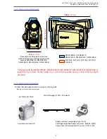
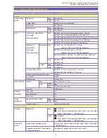
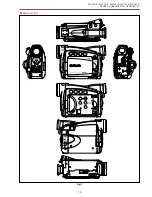
Page 193: ...22 MV750i E MV730i E MV700i E MV700 E MV690 E PARTS LIST Lens Unit Section 1 1 2 3 1 1 1 2 ...

Page 194: ... PARTS SYMBOL PART NO CLASS Q TY DESCRIPTION REMARKS MV750i E MV730i E MV700i E MV700 E MV690 E PARTS LIST 1 XA4 9170 407 000 F 6 SCREW 2 YH8 2013 000 000 C 1 IG METER ASS Y NEW 3 DG3 0551 000 000 C 1 LENS ASS Y NEW ...

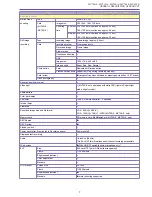
Page 195: ...24 DMC III PARTS LIST 1 10 3 9 5 7 8 6 4 2 3 3 Mechanical Chassis Section 1 ...

Page 196: ...S Y CASSETTE 2 XA1 7140 147 000 C 1 SCREW 3 DA2 2138 000 000 C 4 SCREW 4 DY1 8500 000 000 E 1 DRUM ASS Y NEW 5 DA2 2139 000 000 C 1 WASHER 6 DF1 1703 000 000 C 1 IDLER ASS Y 7 DA2 2116 000 000 C 1 SPRING COIL DRUM 8 DA2 2115 000 000 C 1 SCREW 9 DY1 8501 000 000 B 1 CHASSIS ASS Y SLIDE 10 DA3 2130 000 000 C 1 COVER HOUSING ...

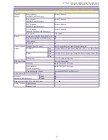
Page 197: ...26 DMC III PARTS LIST 1 2 3 4 5 6 7 8 6 1 9 10 13 11 12 Mechanical Chassis Section 2 ...

Page 198: ...N 4 DF1 1693 000 000 C 1 BRAKE ASS Y TENSION 5 DF1 1694 000 000 C 1 RELEASE ASS Y TENSION 6 DA2 2139 000 000 C 2 WASHER 7 DF1 1704 000 000 C 1 BRAKE ASS Y S 8 DS1 0199 000 000 C 1 SPRING COIL S BRAKE 9 DG1 4505 000 000 C 1 REEL ASS Y T 10 DA2 2220 000 000 C 1 LEVER EJECT 11 DA2 2238 000 000 C 1 BRAKE MAIN T 12 DS1 0198 000 000 C 1 SPRING COIL T BRAKE 13 DF1 1695 000 000 C 1 REVIEW ARM ASS Y ...

Page 199: ...28 DMC III PARTS LIST 2 2 2 2 2 3 3 8 9 2 10 11 12 13 4 6 14 7 5 1 Mechanical Chassis Section 3 ...

Page 200: ...687 000 000 C 1 ROLLER ASS Y GUIDE S 5 DF1 1688 000 000 C 1 ROLLER ASS Y GUIDE T 6 DA2 0780 000 000 C 1 SCREW 7 DF1 1686 000 000 C 1 DRUM BASE ASS Y 8 DA2 2259 000 000 C 1 SCREW 9 DG1 4503 000 000 C 1 MOTOR ASS Y CAPSTAN 10 XA1 7140 147 000 C 1 SCREW 11 DG1 4500 000 000 C 1 ROLLER ASS Y PINCH 12 DA2 2139 000 000 C 1 WASHER 13 DS1 0192 000 000 C 1 SPRING COIL PINCH 14 DA2 2128 000 000 C 1 S LOADING...

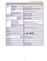
Page 201: ...30 DMC III PARTS LIST 1 3 4 5 8 9 6 10 7 2 11 Mechanical Chassis Section 4 ...

Page 202: ...000 C 1 SCREW 3 DA2 2196 000 000 C 1 BELT TIMING 4 DA2 2197 000 000 C 1 GEAR PULLEY 5 DA2 2190 000 000 C 1 GEAR CONNECT 6 DA2 2140 000 000 C 1 WASHER 7 DA2 2188 000 000 C 1 GEAR WHEEL 8 DA2 2139 000 000 C 1 WASHER 9 DA2 2195 000 000 C 1 GEAR CAPSTAN 10 DG1 4501 000 000 C 1 CHASSIS ASS Y MAIN 11 DA2 2192 000 000 C 1 GUIDE TENSION CAM ...

Page 203: ...TYPE A JPN E B AS 2 1 CA 570S CA 570 N S Product available 3 SDC 8M N S Commercially available Make copy sample pictures if necessary N S Product available WL D82 E 4 CG 570 N S Product available CG 580 N S Product available CB 570 N S Product available 5 6 BP 508 511 512 514 522 535 ...

Page 204: ...D AC E D82 0644 000 000 C 1 CORD AC B D82 0645 000 000 C 1 CORD AC AS 3 DA3 1929 000 000 C 1 COVER TERMINAL BP 514 BP 514 NEW DY1 8242 000 000 C 1 COVER TERMINAL BP 511 BROWN BP 511 512 DY1 8303 000 000 C 1 COVER TERMINAL BP 522 GRAY BP 508 522 535 4 D83 0672 000 000 B 1 WIRELESS CONTROLLER WL D82 E MV750i E MV730i E NEW 5 DY1 8528 000 000 C 1 COVER BATTERY WL D82 E 6 DY1 8530 000 000 C 1 LABEL WI...

Page 205: ...700 E MV690 E PARTS LIST Accessory Section 2 4 SS 900 WD 30 5 WD H30 5 TL 30 5 TL H30 5 N S Product available N S Product available 3 2 3 2 N S Product available FS 30 5 N S Product available IFC 300PCU MV750i E ONLY 1 WIDE ATTACHMENT ...

Page 206: ...i E MV700i E MV700 E MV690 E PARTS LIST 1 D55 0170 000 000 B 1 WIDE ATTACHMENT MV750i E 2 DY4 4764 000 000 C 1 CAP CONVERTER FRONT WD 3 5 TL 3 5 DA1 5766 000 000 B 1 CAP FRONT WD H3 5 TL H3 5 3 DY4 4765 000 000 C 1 CAP CONVERTER REAR 4 D81 1470 000 000 B 1 STRAP SHOULDER SS 900 NEW ...

Page 207: ...CONTINUED PROTECTION AGAINST RISK OF FIRE REPLACE FU1801 ONLY WITH SAME TYPE VD7 2811 001 REPLACE FU3201 FU3202 ONLY WITH SAME TYPE VD7 2241 001 AND REPLACE FU3203 ONLY WITH SAME TYPE VD7 2241 501 IC300 IC301 IC1200 IC1501 IC1800 IC3203 IC103 IC100 IC101 IC102 MAIN P C B FU3202 FU3203 FU1801 FU3201 ...

Page 208: ...01 VD7 2241 001 000 C 1 CHIP FUSE FU3202 VD7 2241 001 000 C 1 CHIP FUSE FU3203 VD7 2241 501 000 C 1 CHIP FUSE R KEY P C B CN100 VS1 7098 027 000 C 1 CONNECTOR 27p NEW CN101 VS1 7098 033 000 C 1 CONNECTOR 33p JACK1 P C B CN51 VS1 7098 025 000 C 1 CONNECTOR 25p NEW CN81 WS1 5524 000 000 C 1 JACK MINI AV CN3551 WS1 6247 000 000 C 1 JACK USB NEW JACK2 P C B CN11 WS1 6367 000 000 C 1 JACK DV NEW CN31 W...

Page 209: ...0 C 1 GEAR PULLEY 27 DA2 2220 000 000 C 1 LEVER EJECT 27 DA2 2238 000 000 C 1 BRAKE MAIN T 29 DA2 2259 000 000 C 1 SCREW 29 DA2 2261 000 000 C 8 SCREW 19 DA3 0161 000 000 C 1 SHIELD CASE HA 19 DA3 0162 000 000 C 1 SHIELD CASE PM 1 19 DA3 0163 000 000 C 1 SHIELD CASE PM 2 17 DA3 0216 000 000 C 1 PLATE MASK 7 DA3 0239 000 000 C 1 SHAFT GRIP BELT 7 DA3 0336 000 000 C 1 SHEET CASSETTE ARM 19 DA3 0732 ...

Page 210: ... E NEW 13 DA3 1118 000 000 B 1 COVER LCD TOP MV700 E NEW 13 DA3 1119 000 000 B 1 COVER LCD TOP MV730i E NEW 13 DA3 1121 000 000 B 1 COVER LCD TOP MV690 E NEW 13 DA3 1122 000 000 C 1 SHEET LCD NEW 15 DA3 1131 000 000 B 1 COVER REAR MV750i E MV730i E NEW 15 DA3 1132 000 000 B 1 COVER REAR MV700i E MV700 E MV690 E NEW 15 DA3 1133 000 000 B 1 LEVER BATTERY EJECT NEW 15 DA3 1134 000 000 C 1 SPRING NEW ...

Page 211: ...W 15 DG3 0331 000 000 C 1 PCB ASS Y LITHIUM MV700i E MV700 E MV690 E NEW 11 DG3 0333 000 000 C 1 FPC RR KEY NEW 7 DG3 0335 000 000 B 1 OPERATION KEY ASS Y MV750i E MV730i E NEW 7 DG3 0336 000 000 B 1 OPERATION KEY ASS Y MV700i E MV700 E MV690 E NEW 17 DG3 0337 000 000 C 1 HINGE ASS Y CVF NEW 13 DG3 0338 000 000 C 1 HINGE ASS Y LCD NEW 13 DG3 0339 000 000 C 1 BACK LIGHT ASS Y LCD NEW 23 DG3 0551 00...

Page 212: ... NEW 35 DY4 4764 000 000 C 1 CAP CONVERTER FRONT WD 3 5 TL 3 5 35 DY4 4765 000 000 C 1 CAP CONVERTER REAR VD7 2241 001 000 C 2 CHIP FUSE VD7 2241 501 000 C 1 CHIP FUSE VD7 2811 001 000 C 1 CHIP FUSE NEW VS1 6596 033 000 C 1 CONNECTOR 33p VS1 7098 021 000 C 3 CONNECTOR 21p VS1 7098 023 000 C 4 CONNECTOR 23p VS1 7098 025 000 C 3 CONNECTOR 25p NEW VS1 7098 027 000 C 1 CONNECTOR 27p NEW VS1 7098 033 0...

Page 213: ...INTERCONNECTION DIAGRAM BLOCK DIAGRAMS CAMERA SECTION 1 CAMERA SECTION 2 CAMERA SECTION 3 SYSTEM CONTROL SECTION SERVO SECTION AUDIO VIDEO SECTION 1 AUDIO VIDEO SECTION 2 POWER SUPPLY SECTION LCD P C B SECTION JACK1 2 SECTION ...

Page 214: ...24 25 IC1501 IC1800 IC3203 IC1200 IC301 IC100 IC101 IC102 A1 1 2 1 2 21 20 CN103 24 25 CN303 CN302 1 2 22 21 1 18 CN1200 1 2 20 21 2 1 33 32 CN1100 CN2000 1 7 CN1501 1 2 23 22 CN101 1 11 CN102 1 2 35 34 CN100 1 2 23 22 CN3201 1 3 A15 B1 B15 CN2101 CN2102 IC300 IC103 IC2302 IC3201 IC2301 IC2300 IC801 IC1103 IC1102 IC2000 CN3202 1 6 1 4 CN3551 CN81 CN43 1 2 24 25 CN51 CN91 IC1601 IC1602 1 2 20 21 CN...

Page 215: ...MIC3 TRST TMS TDI TDO EVF COM EVF B DC DC DC J SW BATT E3 BATT INFO AD BATT BATT BATT BATT MAIN P C B CN901 1 2 3 4 5 6 7 8 9 10 11 12 13 14 15 16 17 18 19 20 21 22 23 24 25 CN903 1 2 3 4 5 6 7 8 9 10 11 12 13 14 15 16 17 18 19 20 21 22 23 24 MO GND MO GND VTR UNREG VTR UNREG VTR UNREG LCD3V ON BL ON LCD EEP SIN1 LCD EEP SCK LCD EEP SOUT LCD EEP CS LCD CS LCD SW 10V LCD SW15V LCD8 5V LCD SW5V LCD ...

Page 216: ...SUB V 2 V 4 V 3 17 VHH 20 VDC 6 CAM 3V VL 2 CCD VL 7 5V VH 16 IV1 7 V 1 42 CCD 7V CCD 15V CAM 3V CCD VH 15V CAM 3V CCD VL 7 5V CCD VH 15V RAWDATA 2 RAWDATA 3 RAWDATA 4 RAWDATA 5 RAWDATA 6 RAWDATA 7 RAWDATA 8 RAWDATA 9 RAWDATA 10 RAWDATA 11 XSG CAM 3V CAM 3V CCD 15V CCD 7V RAWDATA 2 RAWDATA 3 RAWDATA 4 RAWDATA 5 RAWDATA 6 RAWDATA 7 RAWDATA 8 RAWDATA 9 RAWDATA 10 RAWDATA 11 DSP CLK AFE CS AFE RST VG...

Page 217: ... GYRO P GY OUT I SW IRIS PSB IRIS CL IC1501 LV4141W EVF DRIVER 55 BIN 54 GIN 53 RIN 15 HD 8 7 DATA 12 11 57 SYNC IN 1 6 20 43 19 17 18 40 50 DSDOUT 47 VCC 2 39 VCCCOM 38 COMOUT 28 CKV1 27 CKV2 26 STV 25 XSTV 29 XENB 30 ENB 23 XDSG 24 45 49 DSG BOUT GOUT ROUT CKH 2 CKH 1 STH XSTH DSD COM CKV1 CKV2 STV XSTV XENB ENB XDSG DSG B G R CKH2 CKH1 STH XSTH SCLK HDIN VDD 0 VDD 2 VDD 1 VCC 1 LOAD IC1200 BH99...

Page 218: ... L 5 A18 MDATA L 6 B18 MDATA L 7 C18 MDATA L 8 D18 MDATA L 9 A17 MDATA L 10 B17 MDATA L 11 D17 MDATA L 12 A16 MDATA L 13 C16 MDATA L 14 D8 MDATA L 15 A7 MDATA L 16 B7 MDATA L 17 C7 MDATA L 18 D7 MDATA L 19 B6 MDATA L 20 C6 MDATA L 21 A5 MDATA L 22 C5 MDATA L 23 D5 MDATA L 24 B4 MDATA L 25 C4 MDATA L 26 A3 MDATA L 27 B3 MDATA L 28 A2 MDATA L 29 E1 MDATA L 30 D6 MDATA L 31 D4 RAWDATA 2 D2 RAWDATA 3 ...

Page 219: ...EVF 3V ON EVF BL ON EVF 8 5V CN103 B7 A15 A2 A3 A4 B2 B3 B4 B5 A1 A6 A8 A10 A12 B8 B9 B10 B11 B12 B13 B14 B15 CARD ACC CHA LED CARD PRO CARD DET DIAL CW DIAL CCW KEY AD3 CARD DAT2 CARD CMD CARD DAT3 CARD SCK CARD DAT CARD DAT1 LI 3V VTR UNREG DVDD2 7V CN100 12 7 6 4 3 5 21 20 19 15 11 9 2 8 17 SP1 SP2 LCD SW 10V LCD SW15V LCD SW5V LCD3V ON BL ON LCD EEP SIN1 LCD EEP SCK LCD EEP SOUT LCD EEP CS LCD...

Page 220: ...9 C FBR 62 C EC 61 C VS 37 35 34 33 D COM D U D V D W 3 1 2 7 OUT 2 6 IN 2 5 IN 2 IN 1 OUT 1 IN 1 20 19 18 D FGIN D FGPGIN D PGIN 12 C HW 11 C HW 10 C HU 9 C HU 8 C HV 7 C HV 44 L REV 42 L FWD 46 R IN1 47 R IN1 49 R IN2 50 R IN2 2 C U 3 C V 5 C W D VM D VS C VS CFG DPG DFG CAP VS CNT CFG DPG DFG DERR LMO FRBL LMO FRBH LODE ON DRUM ON CAP ON CAP FWD CERR T REEL FG S REEL FG DA CFG DEW MSW AD TAPE T...

Page 221: ... EADDR 4 EADDR 5 TO CAMERA SECTION 3 MAIN P C B EDATA 0 EDATA 1 EDATA 2 EDATA 3 EDATA 4 EDATA 5 EDATA 6 EDATA 7 EDATA 8 EDATA 9 EDATA 10 EDATA 11 EDATA 12 EDATA 13 EDATA 14 EDATA 15 RDY XECS1 XEWRL XDREQ XDACK USB FS EN MACS XRST MACS TDO TCK TMS EDATA 0 to 15 EADDR 0 to 22 XERD XEWRU TRST AUD 2 I MACS1 I CN2101 RMC IN TDI TMS TCK TDO V I O TRST MIC2 MIC3 VTR ON IC3201 CN2900 A4 B9 B8 A7 B10 A1 B7...

Page 222: ... DQ8 DQ7 DQ6 DQ5 DQ4 DQ3 DQ2 DQ1 DQ0 DQMU MCLK CKE XCS XRAS XCAS XWE DQML ADDR 13 ADDR 12 ADDR 11 ADDR 10 ADDR 9 ADDR 8 ADDR 7 ADDR 6 ADDR 5 ADDR 4 ADDR 3 ADDR 2 ADDR 1 ADDR 0 MDATA 15 MDATA 14 MDATA 13 MDATA 12 MDATA 11 MDATA 10 MDATA 9 MDATA 8 MDATA 7 MDATA 6 MDATA 5 MDATA 4 MDATA 3 MDATA 2 MDATA 1 MDATA 0 XTPB TPB XTPA TPA H1B 2 CN2000 H1A 3 H2A 5 H2B 6 CH 1 HEAD DRUM UNIT CH 2 HEAD CN2102 TO J...

Page 223: ...V CAM 3V LPF HA 3V LPF LPF SDRAM 2 7V LPF AVDD 2 7V DIF 2 7V LPF DVDD 2 7V LPF LPF LCD 3V LPF DVDD 2 5V LPF AA 2 7V ON OFF CONT CH1 3 4 8 CH2 CH5 6 CH7 D VM C VM C VS D VS TO SERVO SECTION MAIN P C B TO SEEVO SECTION MAIN P C B NC CN103 DVDD 3V B7 4 3 2 1 5 6 7 8 T3202 4 3 2 1 5 7 6 8 T3201 D3203 Q3202 Q3200 D3205 LPF LPF LCD 15V LCD 10V LPF LCD 8 5V D3201 D3204 D3202 DC DC J SW DC DC J DET A D I ...

Page 224: ... G OUT B OUT G CLAMP GCA GCA GCA B CLK CONTROL D1 VCC2 VDD VCC3 VCC1 STH2 41 RL STH1 CPH3 CPH2 CPH1 STV1 STV2 CPV OEV QH OEH COMDC VCOM CPH3 CPH2 CPH1 STVR STVL CKV DEV Q1H OEH VCOM VGH S I F CLAMP PLL LCD UNIT TIMING GENERATOR LCD SW7 5V Q907 Q908 Q909 1 2 3 6 5 4 6 1 5 3 4 2 1 1 2 4 6 5 3 2 3 6 5 4 CS SK 4 3 2 1 5 7 T4201 6 LCD SW7 5V CN901 VTR UNREG VTR UNREG VTR UNREG LCD 8 5V LCD SW5V LCD 3V ...

Page 225: ...P5V CN91 XTPA TPA XTPG TPG S DET Y I O C I O E ECT SM Y GY OUT P GY OUT AVDD2 7V 3 4 5 6 10 11 14 17 18 20 16 DV JACK S JACK XTPB TPB XTPA TPA CN11 1 2 3 4 CN31 AVDD2 7 AVDD2 7V AVDD2 7 TO AUDIO VIDEO SECTION 2 MAIN P C B CN2102 TO AUDIO VIDEO SECTION 1 MAIN P C B CN2102 CN21 JACK1 P C B JACK2 P C B ZR90 MC A MV750i E DM FV50 ONLY ZR90 MC A MV750i E DM FV50 ONLY ZR90 MC A ZR85 MC A MV750i E MV730i...

Reviews: