


MV750i E, MV730i E, MV700i E, MV700 E, MV690 E
DISASSEMBLING
24
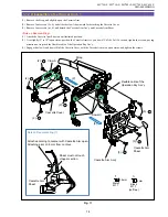
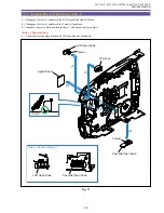
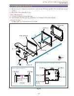
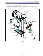
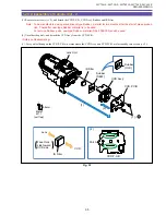
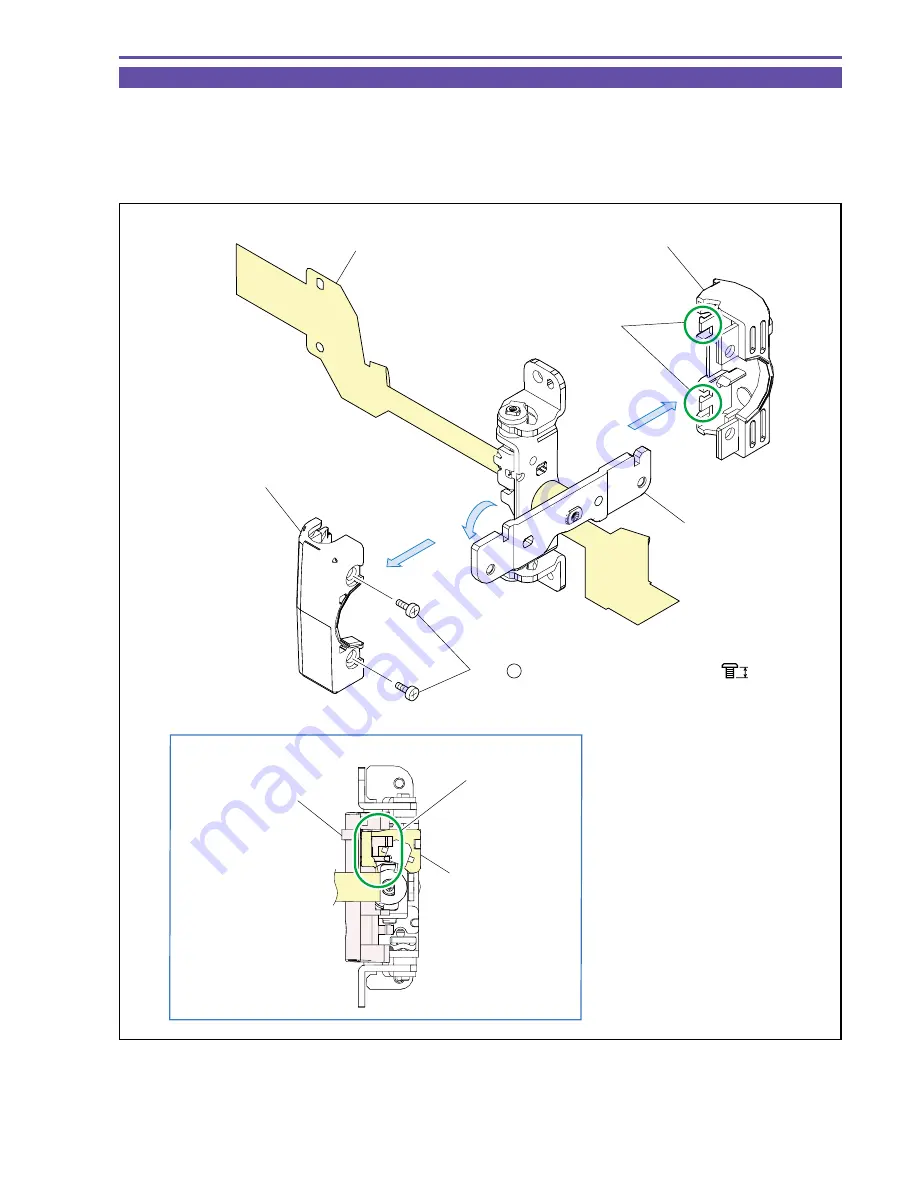
1-20 Disassembly of LCD Hinge Unit - 1
(1) Rotate the Hinge Bracket 90º, and remove two screws (f
×
2).
(2) Disengage the claw A, and detach the Hinge Top Cover and Hinge Bottom Cover.
<Note on Reassembling>
(1) When mounting the Hinge Bottom Cover, pass the LCD FPC above the rib as illustrated.
Fig. 21
f
2.5mm
Metal
M1.7
(1) - f
LCD FPC Ass'y
Hinge Top Cover
Hinge Bracket
(2)
(1)
(2)
Hinge Bottom Cover
Craw A
LCD Bottom Cover
LCD FPC Ass'y
Rib
Note on Reassembling (1)
Summary of Contents for MV750i E
Page 193: ...22 MV750i E MV730i E MV700i E MV700 E MV690 E PARTS LIST Lens Unit Section 1 1 2 3 1 1 1 2 ...
Page 195: ...24 DMC III PARTS LIST 1 10 3 9 5 7 8 6 4 2 3 3 Mechanical Chassis Section 1 ...
Page 197: ...26 DMC III PARTS LIST 1 2 3 4 5 6 7 8 6 1 9 10 13 11 12 Mechanical Chassis Section 2 ...
Page 201: ...30 DMC III PARTS LIST 1 3 4 5 8 9 6 10 7 2 11 Mechanical Chassis Section 4 ...


