OPERATIONS AND
of the
as necessary and, if it finds
error, it
error
the
counter
the
control panel.
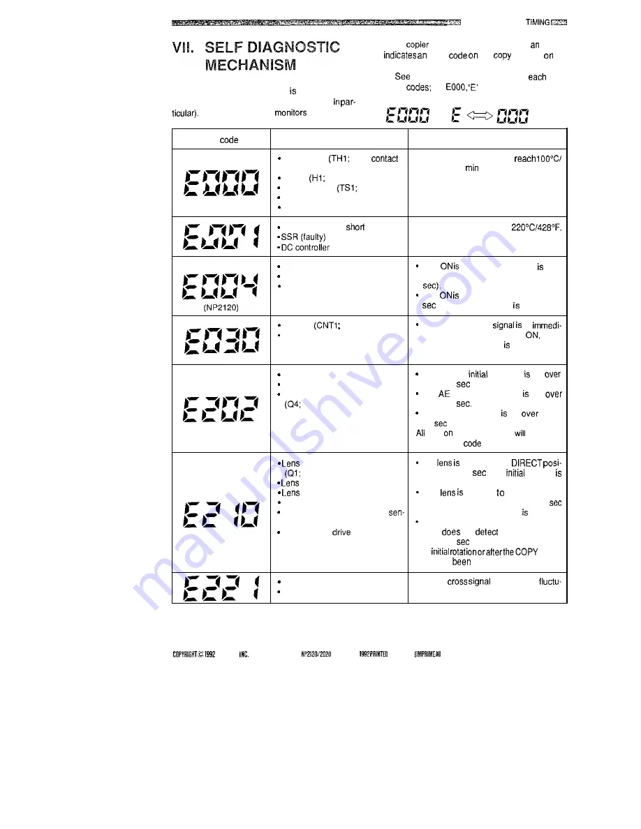
The copier’s microprocessor equipped with a
mechanism to check its condition (sensors,
thetable belowfordescriptionsof
ofthe
error
for
and ‘000’ are flashed
alternately.
The microprocessor
the operation
Error
Cause
Description
Thermistor
poor
or The output of TH1 fails to
open circuit)
212°F within 1
after power-on.
Heater
open circuit)
Thermoswitch
faulty)
SSR (faulty)
DC controller PCB (faulty)
Thermistor (THI;
circuit)
The output of TH1 exceeds
PCB (faulty)
SSR (faulty)
DC controller PCB (faulty)
Fixing heater (open circuit)
SSR
detected while HTRD OFF
immediately after power-on (about 3
SSR
detected continuously for 3
or more while HTRD OFF.
Counter
open circuit)
Normal if the check
‘0’
DC controller PCB (faulty)
ately beforethe countergoes
when
the COPY START key pressed, or at
power-on.
Scanner motor (M2; faulty)
The scanner
operation no!
DC controtler PCB (fautty)
within 15
at power-on.
Scanner home position sensor
The
reverse operation not
faulty)
within 15
The reverse operation not
within
10
after exposure.
keys
the control panel
be locked
without error
indication.
home position sensor
The
not set to the
faulty)
tion within 20
after
rotation
motor (M3; faulty)
started.
wire (faulty)
The
not set the specified
DC controller PCB (faulty)
reproduction ratio position within 20
Blank shutter home position
after the COPY START key pressed.
sor (Q2; faulty)
The blankshutter home position sensor
Blank shutter
wire (faulty)
(Q2)
not
the blank shutter
within 20
after the commencement
of
SART
key has
pressed.
Lamp regulator (faulty)
The zero
(ZXDP) has
DC controller (faulty)
ated.
CANON
CANON
RN.2 OEC.
IN JAPAN
JAPONI d
3-57
Summary of Contents for NP-2020
Page 5: ......
Page 171: ...LL w I n t 0 m a 9zcr 9zcr ...
Page 172: ...I I i I am w m h I I r l I I B m 0 4 u I m ll ...


