CHAPTER 11 TROUBLESHOOTING
COPYRIGHT © 1999 CANON INC. CANON NP6512/6612/7120/7130/7130F REV.0 AUG. 1999 PRINTED IN JAPAN (IMPRIME AU JAPON)
11-44
3.
AE Adjustment
Perform this adjustment if you have replaced any of the following:
• DC controller PCB
• Composite power supply PCB (See p.11-41)
• AE sensor PCB
• Scanning lamp
Making Adjustments
Preparatory Work
• Obtain a newspaper which is more or less even in density. (Avoid ones with photos or large
text characters.)
• Obtain five sheets of white sheets of paper
• Make sure that the intensity of the scanning lamp has been adjusted when you have replaced
the scanning lamp.
• Set the density correction dial (VR107) to the middle setting.
1) Select '40' in service mode.
• The display will indicate '40'.
2) Press the Copy Start key.
• The scanner will move forward, and the scanning lamp will turn on.
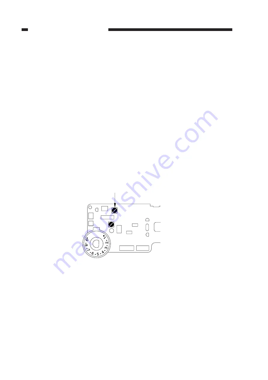
3) Turn VR103 on the DC controller PCB fully clockwise.
Figure 11-262
AE GAIN
VR103
J131
J101
J130
VR102
AE
REF
J107
J103
J104
Summary of Contents for NP6412
Page 6: ......
Page 12: ......
Page 34: ......
Page 46: ......
Page 48: ......
Page 92: ......
Page 144: ......
Page 176: ......
Page 178: ......
Page 192: ......
Page 194: ......
Page 220: ......
Page 222: ......
Page 256: ......
Page 258: ......
Page 282: ......
Page 284: ......
Page 286: ......
Page 384: ......
Page 388: ......
Page 414: ......
Page 424: ......
Page 430: ......
Page 432: ......
Page 434: ......
Page 484: ......
Page 492: ......
Page 502: ......
Page 506: ......
Page 516: ......
Page 599: ...PRINTED IN JAPAN IMPRIME AU JAPON ...


