CHAPTER 2 STANDARDS AND ADJUSTMENTS
2-8
e-2. Routing the Scanner Drive Cable
1. Before Starting the Work
Prepare the following:
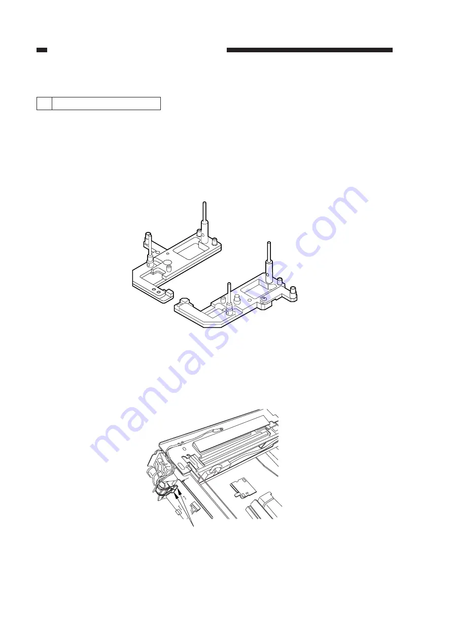
• Mirror positioning tool (FY9-3009)
• Cable clip (FY9-3017)
• Adhesive tape
1) Set the mirror positioning tool as shown.
Figure 2-11
2) Prepare about five strips of adhesive tape (each one about 20 x 50 mm).
3) Remove the copyboard glass.
4) Disconnect the connectors (J101, J131) [1] from the DC controller PCB.
Figure 2-12
[1]
Summary of Contents for NP6412
Page 6: ......
Page 12: ......
Page 34: ......
Page 46: ......
Page 48: ......
Page 92: ......
Page 144: ......
Page 176: ......
Page 178: ......
Page 192: ......
Page 194: ......
Page 220: ......
Page 222: ......
Page 256: ......
Page 258: ......
Page 282: ......
Page 284: ......
Page 286: ......
Page 384: ......
Page 388: ......
Page 414: ......
Page 424: ......
Page 430: ......
Page 432: ......
Page 434: ......
Page 484: ......
Page 492: ......
Page 502: ......
Page 506: ......
Page 516: ......
Page 599: ...PRINTED IN JAPAN IMPRIME AU JAPON ...


