CHAPTER 2 STANDARDS AND ADJUSTMENTS
2-27
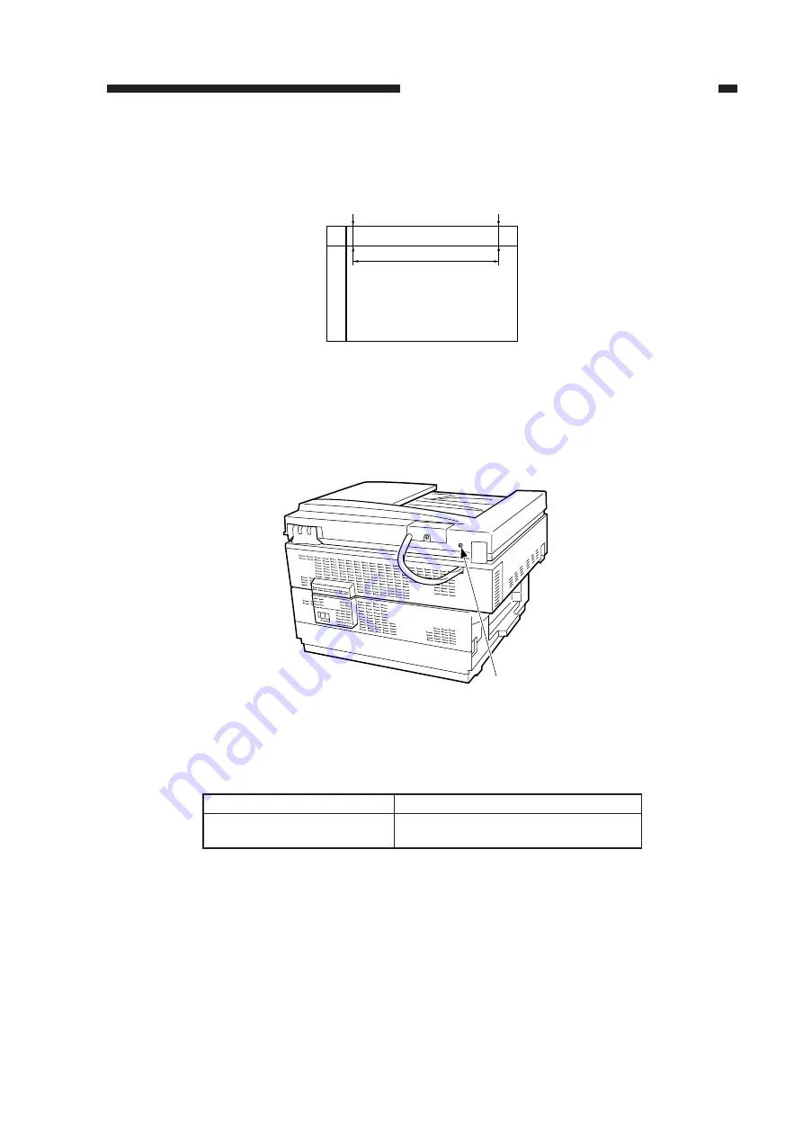
3) Press the Copy Start key to make a copy.
4) Check to make sure that the difference between L1 and L2 on the copy is 1.8 mm (standard) or
less.
Figure 2-44
5) If the difference is not as specified, turn the adjusting screw found to the side of the left hinge
unit to make adjustments.
Figure 2-45
Relationship between Adjusting Screw and L1/L2
Table 2-3
Direction of turn
Clockwise
Counterclockwise
Relationship between L1 and L2
L1 > L2
L1 < L2
Copy image
L1
L2
280mm
L1-L2=0±1.8mm
Adjusting screw
Summary of Contents for NP6412
Page 6: ......
Page 12: ......
Page 34: ......
Page 46: ......
Page 48: ......
Page 92: ......
Page 144: ......
Page 176: ......
Page 178: ......
Page 192: ......
Page 194: ......
Page 220: ......
Page 222: ......
Page 256: ......
Page 258: ......
Page 282: ......
Page 284: ......
Page 286: ......
Page 384: ......
Page 388: ......
Page 414: ......
Page 424: ......
Page 430: ......
Page 432: ......
Page 434: ......
Page 484: ......
Page 492: ......
Page 502: ......
Page 506: ......
Page 516: ......
Page 599: ...PRINTED IN JAPAN IMPRIME AU JAPON ...


