CHAPTER 3 EXPOSURE SYSTEM
COPYRIGHT © 1999 CANON INC. CANON NP6512/6612/7120/7130/7130F REV.0 AUG. 1999 PRINTED IN JAPAN (IMPRIME AU JAPON)
3-5
2.
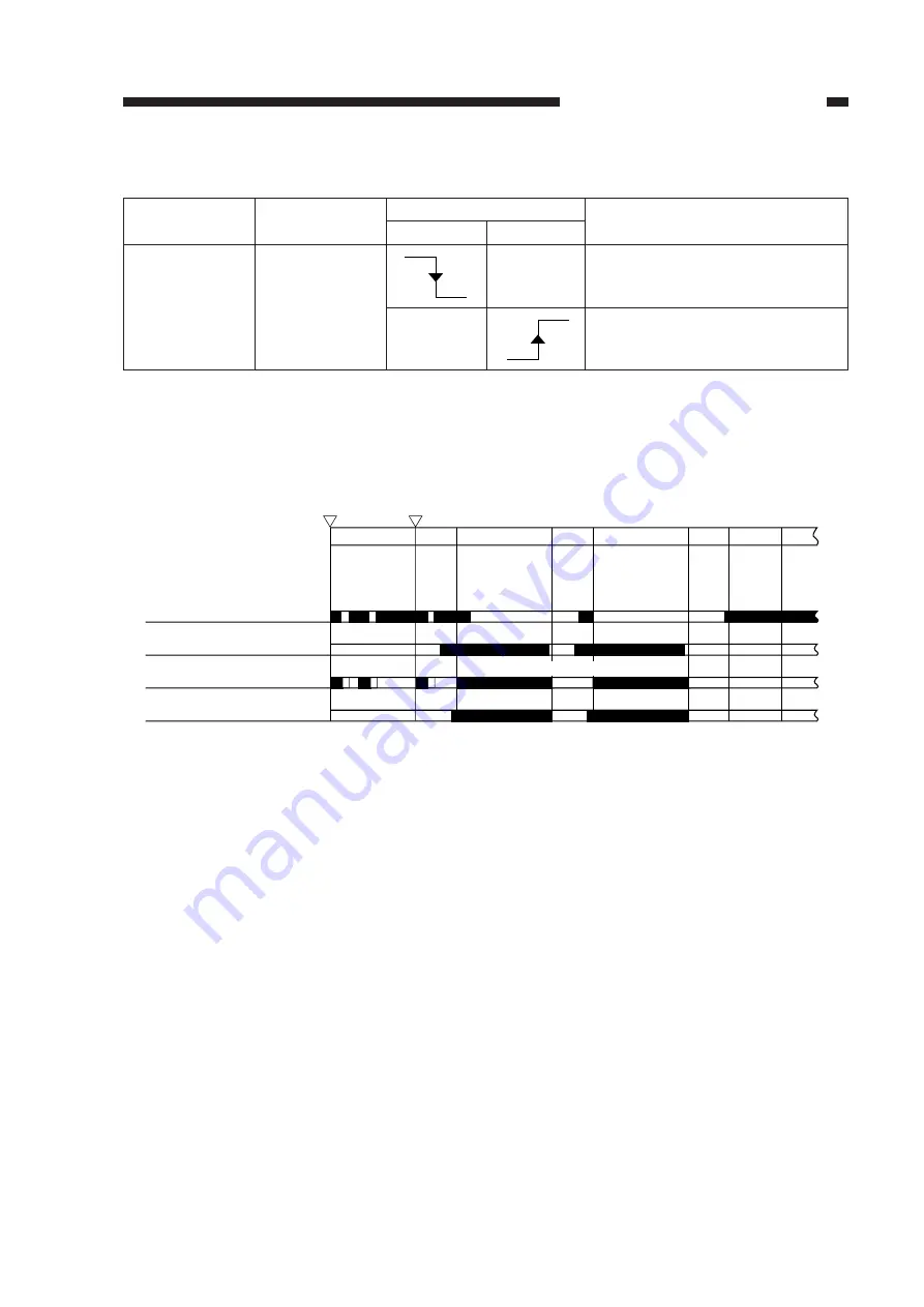
Relationship between Scanner Sensor and Signal
3.
Basic Sequence of Operations (scanner)
Description
• Provides a means of reference for
determining forward movement
distance.
• Stops the scanner moving in re-
verse in 0.1 sec.
Scanner sensor
PS1(scanner
home position
sensor)
Signal
SCHP
Scanner
Forward
Reverse
Table 3-102
,
,,
Copy Start key
Power switch
ON
ON
STBY
INTR
SCFW
Forward
SCFW
SCRV
LSTR STBY
Scanner home position
sensor (PS1)
Scanning lamp(LA1)
Scanner
I
II
SCRV
I
Reverse
Pre-registration roller
paper sensor (Q751)
The microprocessor on the DC controller PCB controls the forward movement distance of the
scanner with reference to the falling edge of the scanner home position signal. The forward move-
ment distance of the scanner varies according to the length of copy paper and reproduction ratio. If
the ratio is less than 130%, the scanner is moved forward as if for A4 (297 mm); if it is 130% or
more, the scanner is moved forward as if for LTR (279 mm).
*For descriptions on how length is detected, see p. 5-7.
I:
Scanner home position detection
II: Lens home position detection
Figure 3-105
Summary of Contents for NP6412
Page 6: ......
Page 12: ......
Page 34: ......
Page 46: ......
Page 48: ......
Page 92: ......
Page 144: ......
Page 176: ......
Page 178: ......
Page 192: ......
Page 194: ......
Page 220: ......
Page 222: ......
Page 256: ......
Page 258: ......
Page 282: ......
Page 284: ......
Page 286: ......
Page 384: ......
Page 388: ......
Page 414: ......
Page 424: ......
Page 430: ......
Page 432: ......
Page 434: ......
Page 484: ......
Page 492: ......
Page 502: ......
Page 506: ......
Page 516: ......
Page 599: ...PRINTED IN JAPAN IMPRIME AU JAPON ...


