CHAPTER 3 EXPOSURE SYSTEM
COPYRIGHT © 1999 CANON INC. CANON NP6512/6612/7120/7130/7130F REV.0 AUG. 1999 PRINTED IN JAPAN (IMPRIME AU JAPON)
3-26
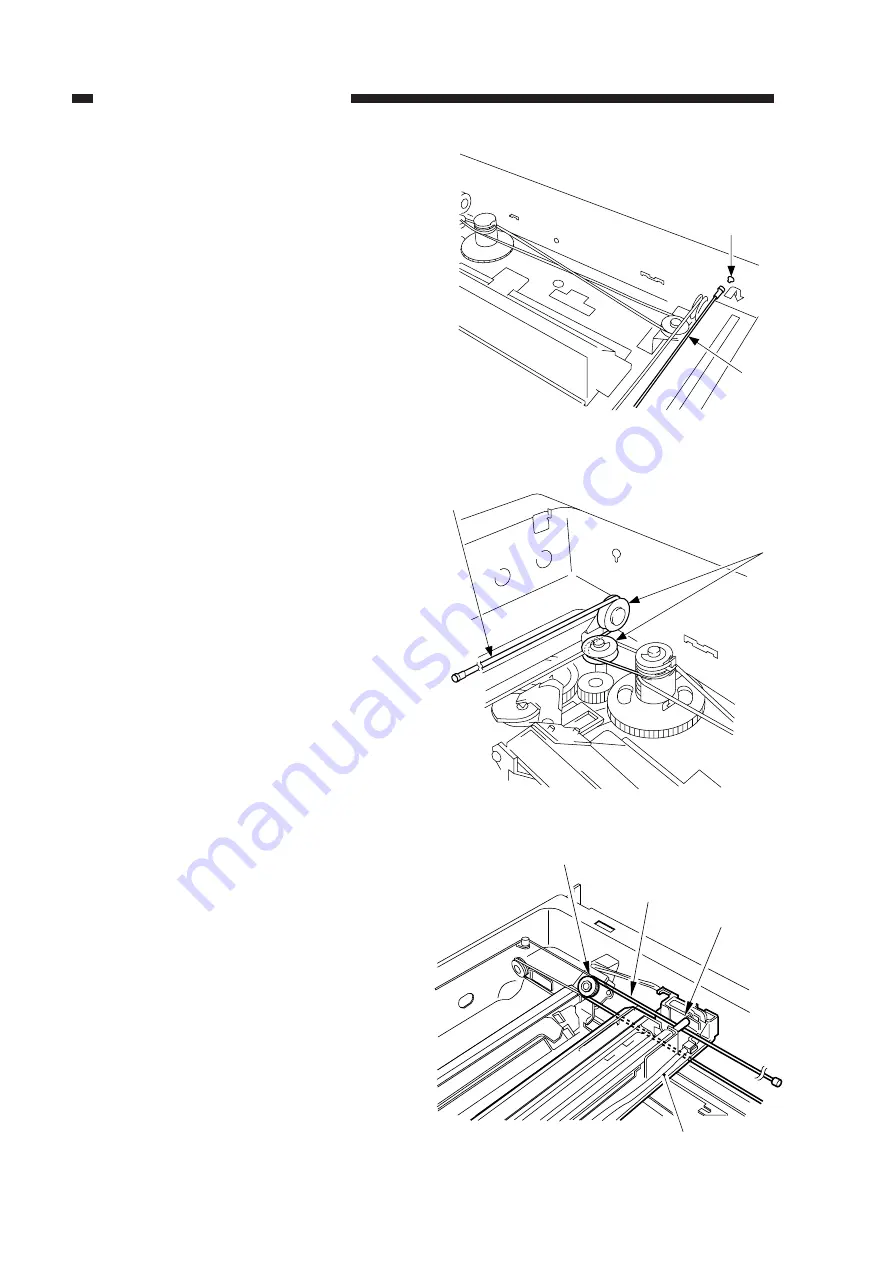
Figure 3-324
Figure 3-326
Figure 3-325
[5]
[10]
[11]
[3]
[7]
[9]
[3]
[12]
6) Lead the shorter end [3] under the No. 1
mirror mount [7], and hook it on the pul-
ley [12] of the No. 2/3 mirror mount as
shown; then, lead it between the No. 1
mirror mount [7] and the scanning lamp
[9].
5) Free the shorter end [3], and hook it on the
pulley [11] on the right rear side.
4) Hook the end of the longer end [5] on the
hole [10] on the right side.
Summary of Contents for NP6412
Page 6: ......
Page 12: ......
Page 34: ......
Page 46: ......
Page 48: ......
Page 92: ......
Page 144: ......
Page 176: ......
Page 178: ......
Page 192: ......
Page 194: ......
Page 220: ......
Page 222: ......
Page 256: ......
Page 258: ......
Page 282: ......
Page 284: ......
Page 286: ......
Page 384: ......
Page 388: ......
Page 414: ......
Page 424: ......
Page 430: ......
Page 432: ......
Page 434: ......
Page 484: ......
Page 492: ......
Page 502: ......
Page 506: ......
Page 516: ......
Page 599: ...PRINTED IN JAPAN IMPRIME AU JAPON ...


