background image

Operation guide

Océ BLM550

Summary of Contents for Oce BLM550+

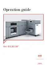
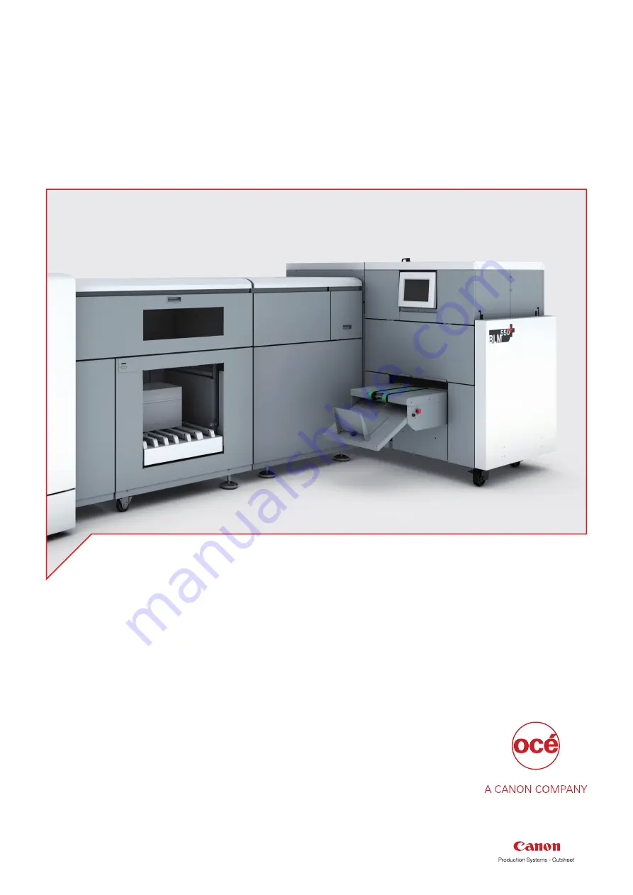
Page 1: ...Operation guide Océ BLM550 ...

Page 2: ...es no representation or warranties with respect to the contents hereof and specifically disclaims any implied warranties of merchantability or fitness for any particular purpose Furthermore Océ reserves the right to revise this publication and to make changes from time to time in the content hereof without obligation to notify any person of such revision or changes Edition 2014 06 US ...

Page 3: ...ook Stacker 24 Run the job 25 Chapter 4 The User Interface 27 The Touch Screen 28 The Job Mimic 31 The BASIC Window 33 The LOAD SAVE Window 35 The ADVANCED Window 37 The CONFIGURE Window 38 The MENU Window 39 Chapter 5 Standard Tasks 41 Load and Save the Job Settings 42 Adjust the Stitch Pitch 43 Open the Connecting Bridge Cover 44 Open and Close the Folder Cover 45 Lift and Lower the Clincher Fra...

Page 4: ...k Stacker infeed 104 Jam at Book Stacker outfeed 105 Change the fuses of the optional Book Stacker 107 Chapter 7 Maintenance 109 About Maintenance 110 Booklet maker cleaning 111 Clean the Former Roller 112 Clean the Polyurethane Strips in the Form Clamp 113 Clean the Trimmings Removal Fingers 115 Clean excess grease from the Stitch Head 117 Lubricate the Stitch Head 118 Apply Grease to the Driver ...

Page 5: ...Chapter 1 Preface ...

Page 6: ...ved for safety Overview of the attention getters Word Icon Indicates WARNING Indicates a warning concerning operations that may lead to death or injury to persons if not performed correctly To use the machine safely always pay at tention to these warnings CAUTION General hazard Indicates a caution concerning operations that may lead to injury to persons if not performed correctly To use the machin...

Page 7: ... actions concerned Safety information Before using this Océ product make sure that you read and understand the safety information which is part of the user documentation You can download the safety information via http downloads oce com or if applicable find it on the user documentation CD DVD that is delivered together with the machine or obtain the safety information from your local Océ represen...

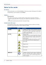
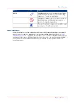
Page 8: ...Notes for the reader 8 Chapter 1 Preface ...

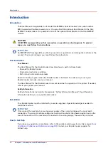
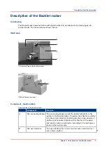
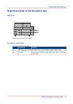
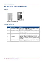
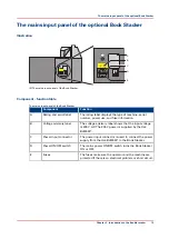
Page 9: ...Chapter 2 Introduction to the Booklet maker ...

Page 10: ...r is installed To make sure you use your Booklet maker correctly read your manual The User Manual for the Booklet maker does not describe the operation of the printer If needed refer to your printer user manual Safety Information Safety information is included in the separate Safety Information Manual Read the safety information before you use your Booklet maker Installation Your Booklet maker mus...

Page 11: ...t Function A The connecting bridge The connecting bridge moves the printed sheets from the printer to the Booklet maker If needed the sheets are rotated into the correct direction Rotation lets the printer operate at optimum print speed Adjustment for the size of the paper and sheet rotation is automatic according to the settings en tered on the touch screen B The user interface The user interface...

Page 12: ...forms and trims the sheets to make a finished book D The Stacker The Stacker collects the finished books E The Book Stacker The optional Book Stacker is a high capacity stacker for the finished books Description of the Booklet maker 12 Chapter 2 Introduction to the Booklet maker ...

Page 13: ... table Right hand side of the Booklet maker Component Function A The stitch wire cabinet The stitch wire cabinet holds the spool of stitch wire B Trim Bin The trim bin collects the paper that is trimmed from the edge of the book Right Hand Side of the Booklet maker Chapter 2 Introduction to the Booklet maker 13 ...

Page 14: ...klet maker ON or OFF When you turn OFF the Booklet maker the cur rent settings are stored C Fuses The fuses make sure the operator and the machine are pro tected if there is an electrical problem or short circuit D Voltage label The voltage label is fitted to the Booklet maker during the installation procedure The voltage label displays the selec ted voltage E Power input connector The power input...

Page 15: ...l The voltage advisory label shows that the input voltage is 230 V AC The 230 V power is supplied by the Océ BLM550 C Power input connector The power input connector is used to connect the power supply from the Océ BLM550 to the Book Stacker D Power ON OFF switch The mains power ON OFF switch turns the Book Stacker ON or OFF E Fuses The fuses make sure the operator and the machine are protected if...

Page 16: ...The mains input panel of the optional Book Stacker 16 Chapter 2 Introduction to the Booklet maker ...

Page 17: ...Chapter 3 How to run the Booklet maker ...

Page 18: ... size of the printed paper The paper size changes during the printing process Measure the set thickness as accurately as possible Use the ruler and the magnifying glass on the bridge cover To get the best accuracy use millimeters to measure the set see Enter the Job Settings on page 21 Enter accurate dimensions into the touchscreen If the book is made from several different types of paper make sur...

Page 19: ...Use the measuring tool supplied with the machine Enter the value into the touch screen Quality instructions Chapter 3 How to run the Booklet maker 19 ...

Page 20: ... turn ON the Booklet maker Result The machine makes this sequence of beeps beep __ beep beep beep beep _____ beep __ beep The touchscreen illuminates and the machine calibrates When READY is displayed on the screen the machine is ready for use Turn ON the Booklet maker 20 Chapter 3 How to run the Booklet maker ...

Page 21: ...ers to measure the set If needed set the Booklet maker to use millimeters Touch MENU Select Supervisor access level Touch MENU CONFIGURE MACHINE OPTIONS Touch mm CLOSE 3 Use these dimensions for the job setting Procedure for a New Job Step Action Information 1 Touch BASIC 2 Enter the paper size Touch PAPER SIZE Enter the dimensions of the paper The job setting is easier if you first select a prese...

Page 22: ...page 33 7 Enter the spine form setting The spine form setting is automatic according to the SET THICKNESS setting If needed the setting can be changed See FORM in Button overview on page 33 8 Enter the trim setting The trim setting is automatic according to the PAGE SIZE and SET THICKNESS settings To change the setting touch TRIM See TRIM in Button overview on page 35 9 Touch CLOSE If needed save ...

Page 23: ... Procedure 1 Touch LOAD SAVE 2 Touch the job name or use the Up arrow or the Down arrow to select the job 3 Touch LOAD 4 Wait until the Booklet maker is ready Procedure for a Saved Job Chapter 3 How to run the Booklet maker 23 ...

Page 24: ...g to the size and thickness of the finished book see Adjust the Stacker on page 53 Adjust the optional Book Stacker Check if the Book Stacker is ready to accept books see Adjust the Book Stacker on page 56 Adjust the Stacker and the optional Book Stacker 24 Chapter 3 How to run the Booklet maker ...

Page 25: ... on page 64 Result During the job Unload books from the Stacker before the Stacker is full The Booklet maker displays no message when the Stacker is full Unload books from the optional Book Stacker see Unload the Book Stacker on page 57 The Booklet maker displays a message when the Stacker is full The Booklet maker stops Empty the trim bin from time to time The Booklet maker displays a message whe...

Page 26: ...Run the job 26 Chapter 3 How to run the Booklet maker ...

Page 27: ...Chapter 4 The User Interface ...

Page 28: ...use the brightness of the touch screen decreases After several hours the touch screen turns off Touch the screen to restore the normal brightness The touch screen takes two or three minutes to reach full brightness If you hear a beep when you operate the touch screen the selected function is not available Some functions are not available when the machine is in operation Some functions and buttons ...

Page 29: ...tion 3 Message List Information and error messages are shown in the MES SAGE LIST To display the information about a message touch HELP then touch the message list Use the right arrow and left arrow to see the help text for each message 4 Job Mimic The job mimic shows the current machine settings 5 Status The STATUS line shows the machine status GREEN The Booklet maker is READY or RUNNING ORANGE P...

Page 30: ...Down arrow to scroll up and down the screen Some text has more than one screen Use the right ar row and left arrow to see the other screens To leave the help text touch HELP or touch X 7 Sheet Counter The sheet counter shows the number of sheets in the gathering area The counter starts again with each book 8 Book Counter The book counter shows the number of books made The counter is reset to zero ...

Page 31: ...ea the broken line shows the fold line the small thick lines show the stitches the arrow shows the original feed edge in the printer 2 Stitch Pitch The stitch pitch is shown only when a non standard setting is selected 3 Sheet thickness Or The sheet thickness in mm is shown NOTE The arrows show a single sheet Set thickness The set thickness in mm is shown NOTE The arrows show the complete set 4 Th...

Page 32: ...shown If the pressure is adjusted the setting is shown in brackets A red X shows that the form function is not active 5 The trim setting is displayed A red X shows that the trim function is not active The Job Mimic 32 Chapter 4 The User Interface ...

Page 33: ...ESS to automatically calculate the SET THICKNESS AUTO Touch SET THICKNESS AUTO to select automatic adjustment of SET THICKNESS Enter the SHEET THICKNESS The sheets are counted when they enter the machine The SET THICKNESS is calculated from the SHEET THICKNESS and the sheet count SHEET THICKNESS Use SHEET THICKNESS to enter the measured thickness of one sheet of paper SHEET THICKNESS determines th...

Page 34: ...SURE to increase or decrease the pressure used to form the spine Touch to increase the amount of spine form Touch to decrease the amount of spine form The range is 9 to 9 The default set ting is 0 THRESHOLD Use THRESHOLD to choose whether a square spine is formed If the SET THICKNESS value is thinner than the THRESHOLD val ue a square spine is not formed If the SET THICKNESS value is thicker than ...

Page 35: ...erisk JOB DETAILS JOB DETAILS shows the settings for each saved job Select the job that you need to view from the job list Touch JOB DETAILS to see a summary of the job settings LOAD Touch the job name or use the Up arrow or the Down arrow to make the selection Touch the LOAD button PADLOCK SYMBOL The padlock symbol shows when a saved job is locked or un locked There is a small padlock symbol next...

Page 36: ...bs in the order they were last used The most recently run job is at the top of the list BY INDEX Touch BY INDEX to list jobs in numerical order the machine gives a number to all jobs that are saved The LOAD SAVE Window 36 Chapter 4 The User Interface ...

Page 37: ...n remain in the gathering area Touch START then touch PURGE SET to clear the set from the machine The book is not stitched or trim med According to the type of error that occurred there can be a pause of 7 seconds before the PURGE SET button will operate For safety reasons this function is disabled when the gathering area cover is open MAKE BOOK If there is a set in the gathering area you can make...

Page 38: ...turn the stitch sensor on or off The default setting is ON Hidden Active PRESET PAPER SIZES The preset paper sizes can be either ISO A sizes or US paper sizes To se lect which preset paper sizes are available touch the relevant button Hidden Active PBS INSTALLED Touch BOOK STACKER to switch off communication to the Book Stacker Only if the Book Stacker is discon nected Hidden Active SHUTTLE Touch ...

Page 39: ...d AXES Touch AXES to re reference individual axes Supervisor access level is needed for this function Other functions on this button are used by the service engineer BRIDGE Touch BRIDGE to re reference the bridge axes Supervisor access level is needed for this function Other functions on this button are used by the service engineer SERVICE OPTIONS This button is used by the service engineer TEST T...

Page 40: ...The MENU Window 40 Chapter 4 The User Interface ...

Page 41: ...Chapter 5 Standard Tasks ...

Page 42: ...ect one REPLACE to over write the previous job with the current job settings SAVE NEW to save the current job with a new name CANCEL to cancel the job save 3 Enter the name for the job on the keyboard 4 Touch OK or CLOSE Load a job 1 Touch LOAD SAVE 2 Touch the job name or use the Up arrow or the Down arrow to select the job 3 Touch LOAD 4 Wait until the Booklet maker has made the adjustments Rese...

Page 43: ...need the Booklet maker to insert the stitches in a non standard position For example to keep the stitches away from the text on the spine of the book Select a non standard stitch pitch 1 Touch BASIC STITCHES 2 Touch AUTO The STITCH PITCH value becomes green 3 Change the stitch pitch value Either use the and or touch the green stitch pitch value to open a numeric keypad 4 Touch STITCHES to close th...

Page 44: ...A 10 Connecting Bridge Cover in the open position A Connecting Bridge Cover When to do If a machine error occurs or for maintenance To clear a paper jam CAUTION Keep your hands clothing and hair away from the belts Procedure 1 Lift the connecting bridge cover Open the Connecting Bridge Cover 44 Chapter 5 Standard Tasks ...

Page 45: ...ing pressure 2 Turn the handle through 90 to unlock 3 Lift the folder cover carefully to the vertical position Close the Folder Cover CAUTION Check that the folder cover will not hit the clincher frame locking handle when you close the folder cover If necessary lift and rotate the clincher frame locking handle to a new position Lift and Lower the Clincher Frame on page 46 1 Lower the folder cover ...

Page 46: ...s A Clincher B Locking Handle C Clincher Frame When to do If a machine error occurs or for maintenance To clear a paper jam in the stitch area To unlock the Booklet maker main deck Lift the Clincher Frame 1 Open the folder cover 2 Turn the locking handle to the left until the thread is disengaged Lift and Lower the Clincher Frame 46 Chapter 5 Standard Tasks ...

Page 47: ...o the right until the handle is tight 3 Check that the locking handle will not be hit by the folder cover when you close the folder cover The locking handle should point towards the middle of the machine If necessary lift and rotate the locking handle to a new position Lift and Lower the Clincher Frame Chapter 5 Standard Tasks 47 ...

Page 48: ...Area Cover Handle When to do If a machine error occurs or for maintenance To access the gathering area The Booklet maker will stop if you open the gathering area cover Procedure 1 Open the connecting bridge cover 2 Use the gathering area cover handle to lift the gathering area cover Open the Gathering Area Cover 48 Chapter 5 Standard Tasks ...

Page 49: ...e error message FOLD BLADE NOT PARKED If the error message is displayed Open the folder cover remove any paper close the fold er cover Touch START then follow the instructions on the screen Wait for the message to clear Then continue with the procedure below If the error message is not displayed Continue with the procedure below CAUTION Keep your hands and fingers clear when you lift the main deck...

Page 50: ...Lift the clincher frame Lift the Clincher Frame on page 46 4 Open the gathering area cover Lift the Clincher Frame on page 46 5 Lift the Booklet maker main deck The main deck lifts to approximately 60 The weight of the main deck is suppor ted by a gas strut Let the gas strut con trol the movement of the main deck Lift the Booklet maker Main Deck 50 Chapter 5 Standard Tasks ...

Page 51: ...ve empty and return the trim bin to the Booklet maker as quickly as possible When to do An error message is displayed on the touch screen when the trim bin is full You can empty the trim bin when you choose For example before you start a print job Procedure 1 Use the handle to open the trim bin 2 Use the side handles to lift and remove the trim bin 3 Empty the trim bin 4 Fit the bottom of the trim...

Page 52: ...s jammed or finished An error message is displayed on the touch screen when the stitch wire is jammed or finished To install a new stitch wire spool Install New Stitch Wire on page 123 Procedure 1 Open the stitch wire cabinet cover The cover is held closed by a magnetic catch Open the Stitch Wire Cabinet 52 Chapter 5 Standard Tasks ...

Page 53: ... table depends on the finished size of the job When you start a new job If the books do not stack correctly C B A 2 1 18 The Stacker A Catch tray adjustment B Collection table C Catch tray A C D B 19 Collection table position A Book size in window B Collection table C Orange plastic hand screw 4 Adjust the Stacker Chapter 5 Standard Tasks 53 ...

Page 54: ... 1 For books that are more than 1 5 mm thick use position 2 2 Set the collection table position accord ing to the size of the book Read the settings through the window These settings are recommendations The settings can change with the size thickness and material of book Make further adjustments if necessary Adjust the Stacker 54 Chapter 5 Standard Tasks ...

Page 55: ... Do not allow another person to help you NOTE Do not use this function when SET THICKNESS is set to AUTO The SET THICKNESS must be the correct setting for the book Procedure 1 Enter the correct settings on the touch screen according to the size and thickness of the job 2 Touch START 3 Open the connecting bridge cover 4 Open the gathering area cover 5 Put the set in the gathering area with the midd...

Page 56: ...n books A Magnetic paper guide Procedure 1 Before you use the Book Stacker make sure the book support is pushed completely to the left There is no need to empty the Book Stacker until the stacker is full 2 If you are making thin books attach the magnetic paper guide above the book outfeed on the Océ BLM550 Insert the loose end of the magnetic paper guide into the slot opposite Standard Tasks of th...

Page 57: ...so that the stack does not slip while you unload the books 2 Remove the books 3 Push the book support completely to the left see Adjust the Book Stacker on page 56 4 Remove the book divider until it is needed Store the book divider on the right hand end of the guide rail of the stacker Unload the Book Stacker Chapter 5 Standard Tasks 57 ...

Page 58: ...witch Replace the mains input fuses Procedure 1 Use your foot to release the docking latch 2 Rotate the Book Stacker away from the Booklet Maker as far as the safety chain allows The safety chain prevents damage to the power and communication cables 3 When you completed your action rotate the Bock Stacker to the docked position The latch clicks when closed Move the Book Stacker 58 Chapter 5 Standa...

Page 59: ...Chapter 6 Error Conditions Problems and Solutions ...

Page 60: ...Procedure 1 Clear the printer error 2 Follow the instructions on the printer If the printer tells you to remove paper from the Booklet maker press START to start the machine 3 Then touch ADVANCED PURGE SET PURGE SET 4 The partial book is delivered to the stacker 5 Discard the book 6 Check the Océ BLM550 screen If an error message is displayed take the corresponding action see Error Messages on pag...

Page 61: ...op The type of error is displayed on the touch screen Error Messages on page 76 Procedure 1 Clear the error The error message on the touch screen tells you about the error 2 Remove all sheets from the Booklet maker 3 Follow the instructions on the printer Clear a Booklet maker error Chapter 6 Error Conditions Problems and Solutions 61 ...

Page 62: ...nues then call your service engineer Is the touchscreen in power save mode see The Touch Screen on page 28 Touch the screen to restore the normal brightness No Yes V Go back to the start of this fault finding table Is the mains power ON OFF switch illuminated No Yes V Call your service engineer Is the Booklet maker turned ON and connected to the mains power supply of the correct type and voltage N...

Page 63: ... mode see The Touch Screen on page 28 Touch the screen to restore the normal brightness No Yes V No further action is needed Calibrate the touchscreen see Calibrate the Touch Screen on page 100 General Problems Chapter 6 Error Conditions Problems and Solutions 63 ...

Page 64: ...ot be made Adjustments to the FORM settings can be necessary for some types of paper Machine Adjustments Machine adjustments can be made while the machine is in operation The PAPER SIZE adjustment is limited to a maximum of 1 mm when the machine is in operation Untidy book problem The finished book is not tidy The sheets are not aligned The book is not folded squarely Are the covers of the books a...

Page 65: ...ness into the touch screen Yes No V Enter the correct SET THICKNESS or SHEET THICKNESS into the touch screen Touch ADVANCED RE REF RE REF to re reference the machine Does the problem persist Yes No V No further action is required Is the paper thin and or curly Yes No V Call your service engineer Increase the TAMPER TIME to give the paper more time to settle Supervisor access level is nee ded see T...

Page 66: ...No V Measure the SET THICKNESS or the SHEET THICKNESS and enter the value in the touch screen Does the problem persist Yes No V No further action is re quired Check the THRESHOLD setting If the SET THICKNESS is less than the THRESHOLD a square spine is not formed see The BASIC Window on page 33 Adjust THRESHOLD if needed Does the problem persist Yes No V No further action is re quired V Adjust the...

Page 67: ...let maker to de fault settings on page 42 Does the problem persist Yes No V No further action is required V Run a standard job using paper of 80 g m 20 lb bond Does the problem persist Yes No V The problem is caused by the cover material or the finish on the cover Change the cover ma terial V Re reference the machine Touch ADVANCED RE REF RE REF to re reference the machine Does the problem persist...

Page 68: ...A 25 Stitch wire jam A Middle wire tube B Large feed gear C Stitch wire jam D Small feed gear Is the number of STITCHES set between 1 and 6 Yes No V Select STITCHES 1 6 see The BASIC Window on page 33 Check the stitch wire spool Is there stitch wire present Yes No 4 Book Quality 68 Chapter 6 Error Conditions Problems and Solutions ...

Page 69: ...r the stitch wire jam see Clear a Stitch wire Jam on page 95 Lubricate the stitch head see Lubricate the Stitch Head on page 118 Does the problem persist Yes No V No further action is required Call your service engineer Stitching problems the book is badly stitched A correctly formed stitch has equal leg length has straight legs the distance between the ends of the stitch legs is approximately 1 m...

Page 70: ...asured the paper size after printing Yes No V Print a sample to the stacker and measure the printed paper Accurate measurement will im prove the book quality V Have you entered the measured PAPER SIZE into the touchscreen Yes No V Enter the correct measured PAPER SIZE into the touchscreen V Touch ADVANCED RE REF RE REF to re reference the machine Does the problem persist Yes No V No further action...

Page 71: ... machine Does the problem persist Yes No V No further action is required Call your service engineer Trimming problem the book is not trimmed to the correct size Is TRIM turned on Yes No V Turn on the TRIM Make sure the size is not larger than the book size or the book will not be trimmed Is the correct trim size entered in the touchscreen Yes No V Enter the correct size in the touchscreen Re refer...

Page 72: ...sist Yes No V No further action is needed Call your service engineer Trimming problem poor trim quality The trim process uses a double edge blade to cut thick books This can leave a small mark in the center of the trimmed edge The visibility of this mark will depend on the paper quality and characteristics 26 Blade witness mark in the center of the book 27 Blade damage mark Are there marks on the ...

Page 73: ...spots on the spine of the book Grease marks near the stitches No Yes V Clean grease from the top of the stitch head see Clean excess grease from the Stitch Head on page 117 Are there dirty marks on the cover of the book near to the spine Marks beside the spine No Yes V Clean the polyurethane form strips see Clean the Polyurethane Strips in the Form Clamp on page 113 4 Book Quality Chapter 6 Error ...

Page 74: ...rmal witness mark A left by the form clamp during spine forming Are there damage marks on the cover of the book near to the spine from the form clamp that are worse than the normal witness mark No Yes V Run a standard job using paper of 80 g m 20 lb bond Does the problem persist Yes No V The problem is caused by the cover material or the finish Change the cover material Call your service engineer ...

Page 75: ...m persist Yes No V The problem is caused by the cover material or the finish Change the cover material Call your service engineer Print a sample to the printer stacker and inspect the pages Is the printer the cause of the damage No Yes V Printer service is required Call your service engineer Book Quality Chapter 6 Error Conditions Problems and Solutions 75 ...

Page 76: ...er than the books can be made To decrease the book cycle time adjust the machine settings decrease the number of FORMS decrease the number of STITCHES decrease the TAMPER TIME touch STOP to clear the message from the screen BOOK DELIVERY TOO FAST Books are being delivered to the stacker too quickly This error can occur when you in sert books into the stacker by hand Press the reset button on the s...

Page 77: ...per The paper dimen sion changes when the paper is printed CHECK THE TRIM BIN The trim bin is either open or full Check the trim bin Empty the trim bin if necessary COVER OPEN A safety cover is open The machine will not operate until the cover is closed DFA INTERFACE No comms Use the mains ON OFF switch Turn the machine OFF then turn the machine ON If the problem continues then call your service e...

Page 78: ...e 85 FLOW ERROR FORMER There is an error at the former Open the folder cover and re move the book If necessary open the main deck to remove the book See Jam in the Folder or For mer Area on page 90 FLOW ERROR GATHER AREA There is a paper jam in the gathering area Open the con necting bridge cover lift the gathering area and remove the paper jam See Jam in the Gathering Area on page 88 FLOW ERROR O...

Page 79: ...Area on page 90 FORM ROLLER NOT PARKED The form roller is in the wrong position Touch START to reset the position Follow the instructions on the screen FORM CLAMP ERROR There is an error at the former Open the folder cover and re move the book If necessary open the main deck to remove the book See Jam in the Folder or For mer Area on page 90 GATHERING AREA COVER OPEN Close the gathering area cover...

Page 80: ...ue See Jam in the Connecting Bridge on page 87 JAM IN GATHERING AREA There is a paper jam in the gathering area Open the con necting bridge cover lift the connecting bridge and remove the paper jam See Jam in the Gathering Area on page 88 JAM IN STACKER AREA There is a paper jam at the outfeed of the machine Re move the jammed books and continue JAM IN STITCHER AREA There is a paper jam in the sti...

Page 81: ...chine needs routine maintenance by the operator See Operator Maintenance on page 110 REBOOT THE MACHINE Use the mains ON OFF switch Turn the machine OFF then turn the machine ON If the problem continues then call your service engineer REMOVE SET FROM FOLD AREA Open the folder cover and re move the set REMOVE SET GATHERING AREA Open the gathering area and remove the sheets REMOVE SET STITCH AREA Op...

Page 82: ...ON OFF switch Turn the machine OFF then turn the machine ON If the problem continues then call your service engineer SHUTTLE No comms Use the mains ON OFF switch Turn the machine OFF then turn the machine ON If the problem continues then call your service engineer SHUTTLE NOT PARKED The shuttle is in the wrong po sition Touch START then follow the instructions on the screen to reset the position S...

Page 83: ... remove the paper close the folder cover SYSTEM ERROR 00 20 40 21 40 22 Touch STOP to clear the mes sage from the screen If the message is not cleared use the mains ON OFF switch Turn the machine OFF then turn the machine ON If the problem continues then call your service engineer SYSTEM ERROR 39 xx Press the reset button on the stacker If the message is not cleared use the stacker mains ON OFF sw...

Page 84: ...e does not clear touch ADVANCED RE REF TRIM BIN OPEN The trim bin is not fitted or is not contacting the safety switch Fit the trim bin TRIM BLADE NOT PARKED The trim blade is in the wrong position Touch START to reset the position Follow the instructions on the screen TRIM No comms Use the mains ON OFF switch Turn the machine OFF then turn the machine ON If the problem continues then call your se...

Page 85: ...e B Gathering Area C Stitch Area D Fold and Forming Areas E Trim Area Jam in the Bridge Infeed Illustration A 30 Paper Jam Location Bridge Infeed A Bridge Infeed Cover Procedure 1 Open the connecting bridge cover Clear Paper Jams Chapter 6 Error Conditions Problems and Solutions 85 ...

Page 86: ...2 Open the bridge infeed cover 3 Remove the jammed paper 4 Close the bridge infeed cover 5 Close the connecting bridge cover Jam in the Bridge Infeed 86 Chapter 6 Error Conditions Problems and Solutions ...

Page 87: ...he Connecting Bridge Procedure 1 Open the connecting bridge cover 2 Remove the jammed paper 3 Close the connecting bridge cover Jam in the Connecting Bridge Chapter 6 Error Conditions Problems and Solutions 87 ...

Page 88: ...the gathering area cover 3 Remove the jammed paper 4 Check the belts are in the correct position Adjust the position of the belts if necessary see illustration Gathering Area Belt Positions 5 Close the gathering area cover 6 Close the connecting bridge cover Jam in the Gathering Area 88 Chapter 6 Error Conditions Problems and Solutions ...

Page 89: ... 46 3 Remove the jammed paper 4 Check for broken or damaged stitch es in the clincher area Manually op erate the clincher to clear any stitch es that are jammed A A Press to manually operate the clinch er 5 Lower the clincher frame See Lift and Lower the Clincher Frame on page 46 6 Close the folder cover Jam in the Stitch Area Chapter 6 Error Conditions Problems and Solutions 89 ...

Page 90: ... 1 Open the folder cover 2 Remove the jammed paper See Jam in the Trim Area on page 93 if you cannot see the paper in the former area 3 Close the folder cover Jam in the Folder or Former Area 90 Chapter 6 Error Conditions Problems and Solutions ...

Page 91: ...above A Trimmer Infeed Conveyor B Former clamp mechanism A C B 33 Access to the Trimmer Infeed Conveyor A Reach in here to access the trim infeed conveyor B Former clamp look in here for paper trimmings C Former clamp mechanism Step Action Information 1 Open the Booklet maker main deck See Lift the Booklet maker Main Deck on page 49 2 Remove the trim bin 4 Jam before the Trimmer Chapter 6 Error Co...

Page 92: ...trimmer infeed conveyor Look down through the former clamp Small pieces of paper trimmings can cover the jam sensor and cause an error message 6 Fit the trimmer infeed conveyor Look down through the former clamp Insert the right hand end of the shaft into the bearing against the spring pressure Rotate the trimmer infeed conveyor so that the green belts are vertical Insert the left hand end so that...

Page 93: ...immings Step Action Information 1 Remove the trim bin 2 Open the trim stop guard See illustration Trim Stop Guard Loosen the 2 orange plastic hand screws to release the locking plates The locking plates can rotate to release the trim stop guard Pull the trim stop guard towards you 3 Remove the jammed book 4 Jam in the Trim Area Chapter 6 Error Conditions Problems and Solutions 93 ...

Page 94: ... green light see illustration Loca tion of the sensor Small pieces of paper trimmings can cover the sensor and cause an error message 5 Close the trim stop guard Push the trim stop guard into position Hold the locking plates in position and tighten the orange hand screws 6 Attach the trim bin Jam in the Trim Area 94 Chapter 6 Error Conditions Problems and Solutions ...

Page 95: ...tch Head A Top location of Middle Wire Tube B Middle Wire Tube C Metal Spring Clip D Feed Gears Step Action Information 1 Cut the stitch wire at position A approximately 50 mm 2 inches from where the stitch wire leaves the stitch wire guide A Detail A Cut stitch wire here 4 Clear a Stitch wire Jam Chapter 6 Error Conditions Problems and Solutions 95 ...

Page 96: ...Pull the stitch wire from the stitch wire guide block Pull stitch wire in direction of arrow 4 Remove the middle wire tube 5 Pull the wire from the stitch head 6 Install the stitch wire into the stitch head See Install the Stitch Wire into the Stitch Head on page 126 Clear a Stitch wire Jam 96 Chapter 6 Error Conditions Problems and Solutions ...

Page 97: ...n and Close the Folder Cover on page 45 2 Lift the clincher frame See Lift and Lower the Clincher Frame on page 46 3 Remove the jammed paper 4 Check for broken or damaged stitch es in the clincher area Manually op erate the clincher to clear any stitch es that are jammed A A Press to manually operate the clinch er 5 Lower the clincher frame See Lift and Lower the Clincher Frame on page 46 6 Close ...

Page 98: ...ock when you do this procedure Force on these parts will damage the stitch head A B C 38 Inspect for stitch wire A Inspect this area for pieces of stitch wire B Wire guide bars C Pivot block Tools and Materials Klüber Isoflex NBU 15 Grease 50g Air duster Supplied with the machine Wire cutters Supplied with the machine Procedure 2 98 Chapter 6 Error Conditions Problems and Solutions ...

Page 99: ...wire holder for stitch wire 4 Remove any stitches or pieces of stitch wire and clean the area with the air duster Use wire cutters to remove any jammed stitches or pieces of stitch wire 5 Lubricate the stitch head Lubricate the Stitch Head on page 118 6 Fit the wire holder Remember to put the wire holder retaining spring in position 7 Close the Booklet maker 8 Start the Booklet maker If the head o...

Page 100: ... a pen or a palm top wand for this procedure Do not use a sharp object Sharp objects damage the screen Procedure 1 Touch the STOP button 5 times 2 Follow the instructions on the touchscreen You must touch the screen where shown as accurately as possible 3 Touch DONE in the center of the screen Calibrate the Touch Screen 100 Chapter 6 Error Conditions Problems and Solutions ...

Page 101: ... This machine uses two fuses in parallel To avoid the risk of fire replace fuses using only the same type and rating Procedure 1 Turn OFF the Booklet maker 2 Disconnect the Booklet maker from the power supply 3 Turn one fuse holder to the left and remove the fuse holder from the Booklet maker 4 Check the fuse 5 If the fuse is blown then replace with a fuse of the correct specification 6 Repeat the...

Page 102: ...orrect position for the shuttle assembly Screw A must be aligned with white gear B If the shuttle assembly does not move to the correct position push the pick up fin gers away from each other by 2 3 mm and try again Repeat if necessary See illustration above 3 Wait until the error message SHUT TLE NOT PARKED is cleared from the screen If the message does not clear check that the shuttle assembly i...

Page 103: ...E is cleared from the screen The shuttle axis re references and the message Shuttle axis moving is displayed When the message list is clear you can continue operation Manually park the Shuttle Chapter 6 Error Conditions Problems and Solutions 103 ...

Page 104: ...ook Stacker infeed Illustration A B 41 Book Stacker infeed A Book Stacker infeed B Book Stacker reset button Procedure 1 Remove the book 2 If you are making thin books attach the magnetic paper guide see Adjust the Book Stacker on page 56 3 Press the reset button on the Book Stacker Clear Paper Jams of the optional Book Stacker 104 Chapter 6 Error Conditions Problems and Solutions ...

Page 105: ...d position The Book Stacker outfeed is not visible The error message JAM AT STACKER OUTFEED is displayed This means a book or some paper trimmings cover the sensor at the Book Stacker outfeed If the Book Stacker outfeed is visible Step Action Information 1 Remove the book if present 2 Check for paper trimmings and re move them if present 4 Jam at Book Stacker outfeed Chapter 6 Error Conditions Pro...

Page 106: ... outfeed is not visible Step Action Information 1 Use your hand to move the pusher to the left against the spring pres sure 2 Remove the book if present 3 Check for paper trimmings and re move them if present 4 Press the reset button on the Book Stacker Jam at Book Stacker outfeed 106 Chapter 6 Error Conditions Problems and Solutions ...

Page 107: ... remove the mains power supply cable before you change the fuses This machine uses two fuses in parallel IMPORTANT To avoid the risk of fire replace fuses using only the same type and rating Procedure 1 Turn OFF the Book Stacker 2 Disconnect the Book Stacker from the power supply 3 Check each fuse 4 If the fuse is blown then replace with a fuse of the correct specification NOTE If the fuse blows a...

Page 108: ...Change the fuses of the optional Book Stacker 108 Chapter 6 Error Conditions Problems and Solutions ...

Page 109: ...Chapter 7 Maintenance ...

Page 110: ...an be identified early Operator Maintenance Plan Interval Task Reference Every week Clean the machine See Booklet maker cleaning on page 111 When the message OPERA TOR MAINTENANCE is dis played on the screen Lubricate the stitch head See Lubricate the Stitch Head on page 118 Clean the former roller See Clean the Former Roller on page 112 Clean the polyurethane strips in the form clamp See Clean th...

Page 111: ...r chemicals or abrasive material Outside of the Booklet maker Use a moist cloth to clean the outside of the Booklet maker Touch screen Clean the touch screen with a clean dry cloth Never use an abrasive material or chemical to clean the touch screen Light pressure with a clean dry cloth is enough to remove fingerprints Do not use too much force Booklet maker cleaning Chapter 7 Maintenance 111 ...

Page 112: ...tep Action Information 1 Enter the correct settings on the touch screen Set the touch screen to the correct PA PER SIZE Set the SET THICKNESS to 4 0 Set the number of STITCHES to 0 Set the number of FORMS to 4 2 Touch START 3 Open the connecting bridge cover 4 Lift the gathering area cover 5 Put 4mm of clean paper in the gath ering area 6 Press the two orange buttons and hold for 9 seconds or unti...

Page 113: ...e Required tools Alcohol wipe or A lint free cloth and alcohol isopropanol IMPORTANT Only use alcohol to clean this part of the machine Other chemicals can damage the machine CAUTION Wear protective gloves when you use the alcohol wipe NOTE If you push the eject rollers the rollers can move together against your hand This movement can alarm you but is not dangerous Illustration A 46 Polyurethane s...

Page 114: ...s when you use the alcohol wipe 3 Reach into the form clamp and clean each of the polyurethane strips There is a polyurethane strip on the face of each side of the clamp Repeat this step until the polyurethane strips are clean 4 Close the folder cover Clean the Polyurethane Strips in the Form Clamp 114 Chapter 7 Maintenance ...

Page 115: ...on the trimmings removal fingers and cause marks on the book 47 Curved marks on the book Required tools Alcohol wipe CAUTION Wear protective gloves when you use the alcohol wipe Illustration A B C 48 Trimmer infeed conveyor viewed from above 1 A Trimmer infeed conveyor B Former clamp mechanism C Reach in here to access the trim infeed conveyor Clean the Trimmings Removal Fingers Chapter 7 Maintena...

Page 116: ...ough the former clamp mechanism see illustration Trim mer infeed conveyor viewed from above 1 Wear protective gloves when you use the alcohol wipe 4 Rotate the conveyor shaft by half a turn 1 Hold the shaft and push to the right against spring pressure to disengage the shaft from the drive pin 1 2 3 2 Rotate the shaft by half a turn 3 Align the shaft with the drive pin and release 5 Clean the four...

Page 117: ...nformation 1 On the user interface touch AD VANCED STITCHER UP STITCH ER UP The folder cover must be closed This ac tion moves the stitch head to the correct position for lubrication 2 Open the folder cover Open and Close the Folder Cover on page 45 3 Lift the clincher frame Lift and Lower the Clincher Frame on page 46 4 Clean grease from the sides of the stitch head 5 Lower the clincher frame 6 C...

Page 118: ...ypes of grease do not protect the stitch head IMPORTANT Only apply the grease as shown If you apply additional grease the paper will become stained Step Action Information 1 Trim the first 2 5 mm from the noz zle 51 Tip of the nozzle 52 Trim the nozzle of the tube of grease 2 Remove the cap from the tube of grease 3 Fit the nozzle to the tube of grease 4 On the user interface touch AD VANCED STITC...

Page 119: ... You will see that the stitch head is in the STITCHER UP position 6 Use the supplied air duster to re move dust from the stitch head 7 Remove the wire holder from the stitch head Move the wire holder retaining spring A to the right Remove the wire holder B Lubricate the Stitch Head Chapter 7 Maintenance 119 ...

Page 120: ...f the line of grease NOTE Make sure that you apply the grease in an upward direction from the bot tom of the driver bar 54 Driver bar A Driver B Apply grease here C Driver bar NOTE Only apply the grease as shown If you apply addi tional grease the paper will become stained 55 Apply the grease to the driver bar A Start B Stop 2 Fit the wire holder Apply Grease to the Driver Bar 120 Chapter 7 Mainte...

Page 121: ...urface of the wire feed cam and the feed lever See the Lubricate the wire feed cam illustration above 0 4 2 Lower the Booklet maker main deck 3 Lower the clincher frame See Lower the Clincher Frame on page 47 4 Close all of the covers 5 Make some test books 6 Clean excess grease from the top of the stitch head See Clean excess grease from the Stitch Head on page 117 Lubricate the wire feed cam Cha...

Page 122: ... Procedure 1 Touch MENU 2 Touch and hold RESET A red line appears The red line fills from left to right Hold RESET until the red line reaches the right hand side 3 Touch MENU Reset the Operator Maintenance Counter 122 Chapter 7 Maintenance ...

Page 123: ...begin Lift the Booklet maker main deck See Lift the Main Deck on page 49 Remove the Stitch wire from the Stitch Head Illustration A B C 57 Stitch wire Guide Block A Stitch wire Guide Block B Stitch wire C Felt wire cleaning pads Step Action Information 1 Cut the stitch wire to the right of the stitch wire guide block A Detail A Cut here 2 Pull the stitch wire from the stitch wire guide block 4 Ins...

Page 124: ...Step Action Information 3 Fit a new stitch wire spool Fit a New Stitch wire Spool on page 125 Remove the Stitch wire from the Stitch Head 124 Chapter 7 Maintenance ...

Page 125: ...osen the end of the stitch wire from the edge of the stitch wire spool 6 Use wire cutters to remove the damaged end of the stitch wire Remove enough stitch wire to leave the end of the stitch wire clean and straight 7 Feed the stitch wire through the stitch wire guide 8 Install the stitch wire Install the Stitch Wire into the Stitch Head on page 126 Fit a New Stitch wire Spool Chapter 7 Maintenanc...

Page 126: ...f the stitch wire be tween the felt wire cleaning pads A Detail A Felt Wire Cleaning Pads 4 Push the stitch wire into the stitch wire guide block Push stitch wire in direction of arrow 5 Push the stitch wire as far as possi ble A Detail A Make sure the stitch wire runs be tween the wire feed rollers and into the mid dle wire tube Install the Stitch Wire into the Stitch Head 126 Chapter 7 Maintenan...

Page 127: ...ion 1 Close the stitch wire cabinet 2 Lower the Booklet maker main deck Lower the Clincher Frame on page 47 3 Lower the clincher frame 4 Close the folder cover 5 Close the connecting bridge cover Close the Booklet maker Chapter 7 Maintenance 127 ...

Page 128: ...thickness of the job The stitch wire loads automatically during the stitch head cycle 4 Check that the stitch wire is loa ded Check that a stitch is made If needed repeat the previous step If a stitch is still not made repeat the proce dure Install the Stitch wire into the Stitch Head Install the Stitch Wire into the Stitch Head on page 126 5 Reset the number of stitches on the touch screen Feed t...

Page 129: ...e If paper trimmings collect on the trim stop the books are not trimmed square Illustration B C A 58 Trim Stop Guard A Orange Plastic Hand Screw B Locking Plate C Trim Stop Guard A 59 Trim Stop A Trim Stop Step Action Information 1 Remove the trim bin 4 Clear paper from the trim stop Chapter 7 Maintenance 129 ...

Page 130: ...te to re lease the trim stop guard Pull the trim stop guard towards you 3 Check the trim stop and remove any pieces of trimmed paper 4 Close the trim stop guard Push the trim stop guard into posi tion Hold the locking plates in position and tighten the orange hand screws 5 Attach the trim bin Clear paper from the trim stop 130 Chapter 7 Maintenance ...

Page 131: ...Appendix A Specifications ...

Page 132: ...ivity Maximum rotation sheet size 320 mm x 227 mm Minimum rotation sheet size 210 mm x 203 mm The cross track dimension of the sheet before rotation must be at least 7 mm greater than the in track dimension A 12 6 x 8 9 B 8 8 3 A Stitch fold line B indicates original lead edge from the printer Stock Range 80 160 g m normal paper types 60 250 g m dependent on paper type and quality Book Thickness M...

Page 133: ...e and bridge covers 702 kg 1548 lbs Book Stacker 150 kg 330 lbs Power Supply Adjustable to 200 208 220 230 and 240V 50 60Hz single phase Power Consumption Océ BLM550 Stand by 92VA 75W In operation 700VA 500W Book Stacker Stand by 35VA 16W In operation 75VA 53W Noise Emission Stand by ambient In operation 66 dB A peak 87 dB A Approvals Complies with CE and UL Conforms to FCC rules Part 15 Class A a...

Page 134: ...Specifications 134 Appendix A Specifications ...

Page 135: ...Appendix B Declaration of Conformity ...

Page 136: ...f laws of Member States relating to electrical equipment designed for use within certain voltage limits EN 60950 1 2006 ed 2 A11 2009 A1 2010 A12 2011 EMC 2004 108 EC Council Directive on the approximation of laws of Member States relating to electromagnetic compatibility EN55022 2010 Class A EN55024 2010 EN61000 3 2 2006 A1 2009 A2 2009 EN61000 3 3 2008 RoHS 2006 65 EC Council Directive WEEE 2002...

Page 137: ......

Page 138: ...w canon ca Canon Europa Inc www canon europe com Canon Latin America Inc www cla canon com Canon Australia PTY Ltd www canon com au Canon China Co Ltd www canon com cn Canon Singapore PTE Ltd www canon com sg Canon Hongkong Co Ltd www canon com hk CANON INC Océ Holding B V 2014 ...

Reviews: