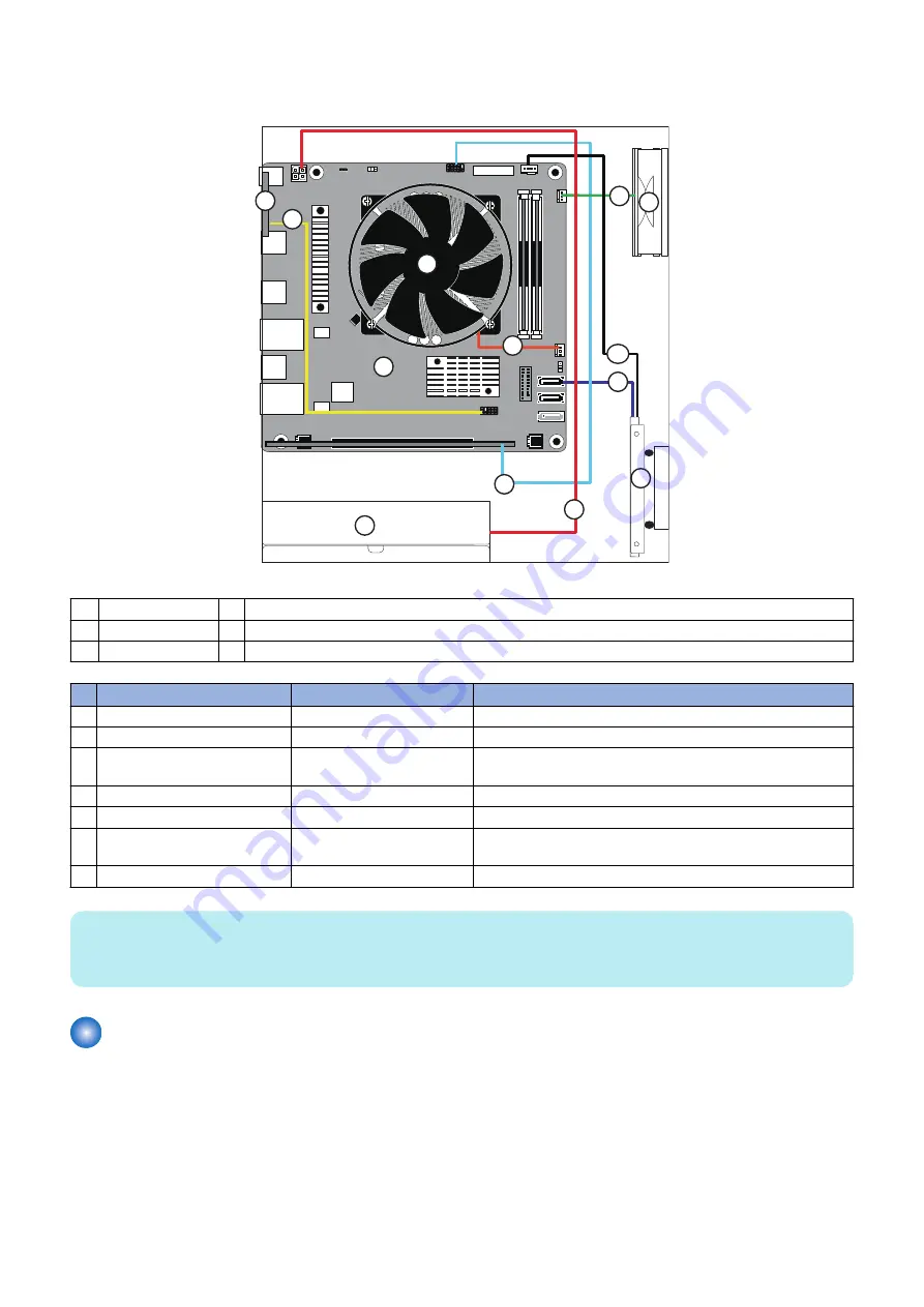
■ imagePRESS Server internal cable connections
The following diagrams illustrate the internal cable connections between hardware components and the motherboard.
C
D
A
B
E
F
4
2
6
5
3
1
7
Figure 5: Internal cable connections
A
Power supply
D
Motherboard
B
CPU
E
Storage device
C
Chassis fan
F
Service switchboard
Cable key
From
To
1
4-pin power supply cable
Power supply
ATX Power Connector on motherboard (4p) (PWR2)
2
Storage device data cable
Storage device data connector SATA0 on motherboard
3
Storage device SATA power ca-
ble
Storage device
SATA HDD PWR Connector (PW9)
4
CPU fan cable
CPU fan
CPU FAN Connector (CPU_FAN)
5
Chassis fan cable
Chassis fan
System FAN Connector (SYS_FAN_1)
6
Service switchboard cable
Service switchboard connec-
tor
TYAN Module Header (DBG_HD1)
7
10-pin power button cable
Printer interface board (J351) J29 connector on motherboard
NOTE:
The cable colors in the illustration are not the actual cable colors.
For detailed locations of the connectors on the motherboard, see
“Motherboard parts and connectors” on page 26
.
Removing and replacing imagePRESS Server components
Before replacing costly components, be sure to verify the connections between the printer and the
imagePRESS Server
. Also,
verify the connections of each replaceable
imagePRESS Server
component. For more information about troubleshooting, see
.
The following sections describe how to remove and install replaceable parts on the
imagePRESS Server
:
• Printer interface board
• DIMM
• Battery
• Motherboard
• CPU and CPU cooling assembly
3. REPLACING PARTS
20
Summary of Contents for P 400
Page 7: ...Introduction 1 Introduction 2 Specifications 7...
Page 16: ...Using the imagePRESS Server 2 Using the imagePRESS Server 11...
Page 21: ...REPLACING PARTS 3 Replacing parts 16...
Page 51: ...INSTALLING SYSTEM SOFTWARE 4 Installing system software 46...

