CHAPTER 7 EXTERNALS/AUXILIARY MECHANISMS
COPYRIGHT © 1999 CANON INC. CANON PC800s/900s REV.0 AUG. 1999 PRINTED IN JAPAN (IMPRIME AU JAPON)
7-17
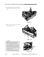
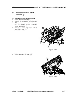
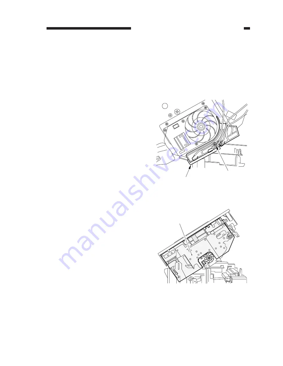
Figure 7-318
Figure 7-319
[1]
[2]
[3]
D.
Main Motor/Main Drive
Assembly
1.
Removing the Main Motor Unit
1) Remove the drum cartridge.
2) Remove the composite power supply
PCB.
(See E.2. “Removing the Composite
Power Supply PCB.”)
3) Remove the screw [1], and detach the
high-voltage PCB [2].
4) Remove the insulating sheet [3].
Summary of Contents for PC920
Page 12: ......
Page 34: ......
Page 36: ......
Page 48: ......
Page 50: ......
Page 92: ......
Page 94: ......
Page 122: ......
Page 124: ......
Page 162: ......
Page 164: ......
Page 180: ......
Page 206: ......
Page 240: ......
Page 242: ......
Page 256: ......
Page 263: ......
Page 265: ......
Page 355: ......
Page 383: ......

