COPYRIGHT © 1999 CANON INC. CANON PC800s/900s REV.0 AUG. 1999 PRINTED IN JAPAN (IMPRIME AU JAPON)
11-72
CHAPTER 11 TROUBLESHOOTING
11-72
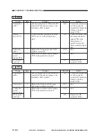
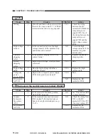
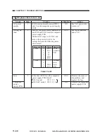
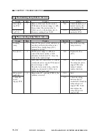
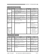
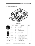
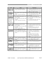
21 The blanking lamp fails to turn on.
YES/NO
NO
YES
Cause
Side blank-
ing PCB
DC control-
ler PCB
Step
1
Checks
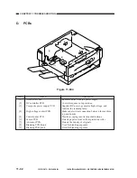
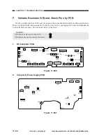
Remove J106 from the DC control
PCB, and set the meter range to 1 k
Ω
;
then, connect the meter probes to
J106-1 and -2 on the harness side. Is
the meter reading about 20
Ω
?
Action
Check the harness; if
normal, replace the
side blanking PCB.
Replace the DC
controller PCB.
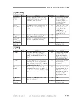
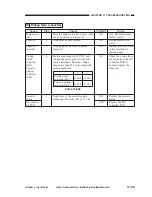
22 The scanning lamp fails to turn on.
YES/NO
NO
NO
NO
YES
NO
Cause
Scanning
lamp
Fuse (FU1)
Lamp
DC control-
ler PCB
Composite
power
supply PCB
Step
1
2
3
4
Checks
Turn off the power switch, and discon-
nect the power plug from the power
outlet.Is the scanning lamp (LA1)
mounted correctly?
Set the meter range to 1 k
Ω
, and
connect the meter probes to both
terminals of the fuse (FU1). Does the
index of the meter swing?
Disconnect the connector J910 from th
ecomposite power supply PCB, and set
the tester range to 1k
Ω
.
Does the tester index swing when the
probes are connected to J910-1 and
J910-3 on the lamp side?
Replace the DC controller PCB. Is the
problem corrected?
Action
Mount the scanning
lamp correctly.
Replace the fuse
(FU1).
Check the cable from
the composite power
supply PCB to the
lamp; if normal,
replace the lamp.
End.
Check the wiring
between the DC
controller PCB and the
composite power
supply PCB; if nor-
mal, replace the
composite power
supply PCB.
Summary of Contents for PC920
Page 12: ......
Page 34: ......
Page 36: ......
Page 48: ......
Page 50: ......
Page 92: ......
Page 94: ......
Page 122: ......
Page 124: ......
Page 162: ......
Page 164: ......
Page 180: ......
Page 206: ......
Page 240: ......
Page 242: ......
Page 256: ......
Page 263: ......
Page 265: ......
Page 355: ......
Page 383: ......

