background image

II. EXTERNALS

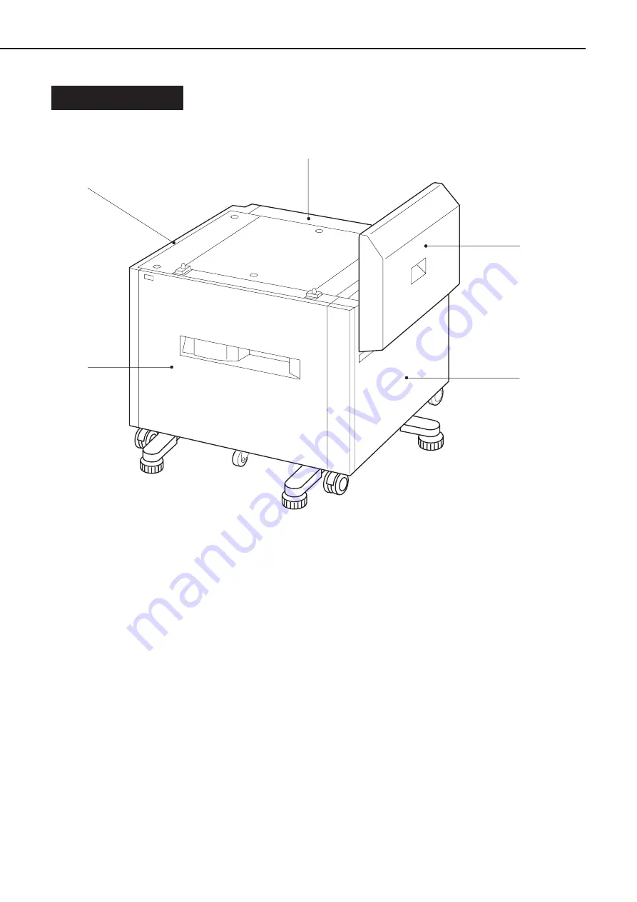
A. Locations

Front cover

Left cover

Right cover

Feed cover

Rear cover

Figure 3-2-1

Following the procedures described in this section, remove the covers when cleaning or check-
ing inside the paper deck.

The removal procedures of the covers that can be removed simply by taking out the screws

without removing other parts are omitted.

3 - 2

CHAPTER 3

Summary of Contents for PD-82

Page 1: ...SERVICE MANUAL REVISION 0 COPYRIGHT 1999 CANON INC CANON 2000 SHEET PAPER DECK PD 82 REV 0 JAN 1999 PRINTED IN JAPAN IMPRIME AU JAPON RY8 1395 000 JAN 1999 2000 SHEET PAPER DECK ...

Page 2: ...of this manual should be strictly supervised to avoid disclosure of confidential information Prepared by PERIPHERAL PRODUCTS QUALITY PLANNING DIV PERIPHERAL PRODUCTS TECHNICAL DOCUMENTATION DEPT CANON INC 5 1 Hakusan 7 chome Toride City Ibaraki Pref 302 8501 Japan ...

Page 3: ...ctrical and mechanical systems Chapter 3 The Mechanical System Explanation of mechanical operation disassembly reassembly and adjustment procedures Chapter 4 Troubleshooting Maintenance and servicing measurement and adjustments troubleshooting procedures etc Appendix General circuit diagram and list of signals Information in this manual is subject to change as the product is improved or redesigned...

Page 4: ... laser beam printer final pages were printed on AGFA Selectset avantra 25 All graphics were produced with Macromedia FreeHand J and all documents and page layouts were created with QuarkXPress E The video images were captured with SONY degital video camcorder and Radius PhotoDV capture board system and modified with Adobe Photoshop J ...

Page 5: ... Locations 3 2 B External Covers 3 3 III MAIN UNITS 3 5 A Drive Unit 3 5 B Pick up Unit 3 5 C Paper Feed Unit 3 6 D Tray 3 6 IV MAIN PARTS 3 7 A Locations 3 7 B Lifter 3 8 V SWITCHES 3 13 A Locations 3 13 B Paper Level Detection Switches 3 14 C Paper size Detection Switches 3 14 VI SENSORS 3 15 A Locations 3 15 B Registration Paper Sensor 3 16 C Paper Jam Sensor 3 16 D Tray Paper out Sensor Paper ...

Page 6: ...ical Adjustment 4 17 B Electrical Adjustment 4 17 C LEDs test pins jumpers and switches on PCB 4 17 VII MAINTENANCE AND SERVICING 4 20 A Periodic Replacement Parts 4 20 B Expected Lives of Consumable Parts 4 20 C Regular Servicing Schedule 4 20 D Standard Tools 4 20 E Special Tools 4 20 F List of Lubricants and Cleaners 4 20 VIII LOCATION OF CONNECTORS 4 21 APPENDIX I GENERAL CIRCUIT DIAGRAM A 1 I...

Page 7: ...CHAPTER 1 PRODUCT INFORMATION I FEATURES 1 1 II SPECIFICATIONS 1 2 III PARTS OF THE PAPER DECK 1 3 IV INSTALLATION 1 5 ...

Page 8: ......

Page 9: ... to make continuous printing in large volume 2 Status LED The LED on the front of the paper deck allows the user to check the status of the paper deck easily 3 Stand alone mode switch The paper deck can be operated without printer by turning ON the stand alone mode switch allowing the service technician to perform the service mode easily ...

Page 10: ...e Published noise Sound power level 1B 10dB 7 1 B or less during printing level based on ISO 9296 6 4 B or less standby Note Sound pressure level 53 dB or less during printing Bystander position 48 dB or less standby 5 Dimensions 629 width 520 depth 651 height mm 6 Weight About 30 kg 7 Power supply 100 to 127 V 50 60 Hz 220 to 240 V 50 Hz Voltage tolerance 10 Note Value when the printer is equippe...

Page 11: ...ARTS OF THE PAPER DECK A Appearance Figure 1 3 1 Figure 1 3 2 1 Positioning pins 2 Paper feed unit 3 Paper size regulation plates 4 Lifter 5 Status LED 6 Interface connector 7 Power receptacle 1 3 CHAPTER 1 ...

Page 12: ...B Cross Sectional Views Figure 1 3 3 1 Lifter 2 Paper size regulation plates 3 Pick up roller 4 Feed roller 1 5 Feed roller 2 6 Registration rollers 7 Separation roller 1 4 CHAPTER 1 ...

Page 13: ...ers were scratched or deformed during shipment 5 Open the tray remove the 2 spacers and peel off the tape 6 Peel off the tape holding the latch of the paper guide 2 Connecting to the printer 1 Carry the paper deck to the installation location and lock the casters 2 Rotate the adjusters to install on the floor 3 Open the feed unit 4 Line up the printer and paper deck in the same direction and have ...

Page 14: ......

Page 15: ... ground level indicating that the signal is not being output A signal that is L or has a slash in front of its name is active at ground level and inac tive at the supply voltage level There is a microcomputer in this paper deck But as the internal operation of the micro computer cannot be checked an explanation of the operation of the microcomputer has been left out As it is assumed that no repair...

Page 16: ......

Page 17: ...ontroller PCB The paper deck driver drives the solenoids and motors according to various commands coming from the option controller through the serial communication line The paper deck driver sends sensor and switch data to the option controller through the serial communication line Figure 2 1 1 2 1 CHAPTER 2 Option controller PCB Paper deck driver PCB Power supply Registration clutch Pick up sole...

Page 18: ...2 1 3 2 LIFTS J314 3 1 2 5V J304 5 3 4 J304a 4 6 5 J304 8 6 7 J304a 1 3 2 J307 3 1 2 J307a 7 9 8 J307 6 4 5 J307a 4 6 5 J307 9 7 8 J307a 1 3 2 Paper jam sensor Tray paper out sensor Door sensor Paper surface sensor Paper level detection switch Paper size detection switch Paper size detection switch PCB Paper level detection switch PCB Paper deck driver PCB Detects the level of paper L when the sen...

Page 19: ... motor SPM2 FED1AD FED1AND FED1BD FED1BND J207 1 2 3 4 J315a 1 2 3 4 FEED MOTOR ROTATION CONTROL signal J315 5 4 3 2 Pick up motor SPM3 FED2AD FED2AND FED2BD FED2BND J210 1 2 3 4 J305a 1 2 3 4 PICK UP MOTOR ROTATION CONTROL signal J305 4 3 2 1 24V J207 2 1 J303 1 2 Registration clutch REGCLD Registration roller rotates when L CL1 J304a 8 7 J303a 1 2 J304 1 2 24V J306a 2 1 Pick up solenoid SL1 PUPS...

Page 20: ...rs the pick up roller to the print paper surface As the pick up roller turns the paper is fed to the paper feed unit The paper passes through the registration paper sensor PS1 and stops when it touches the registration roller When the registration clutch CL1 turns ON the paper is fed to the printer There are two photointerrupters PS1 and PS2 in the paper path to detect paper If the paper does not ...

Page 21: ... SOLENOID DRIVE signal PUPSLD REGISTRATION CLUTCH DRIVE signal REGICL SPM1 Lifter motor SPM2 Feed motor SPM3 Pick up motor SL1 Pick up solenoid CL1 Registration clutch Lifter Option controller PCB Pick up roller Separation roller Feed roller 1 Registration roller Feed roller 2 Paper deck Serial line SPM2 FEED MOTOR DRIVE signal ...

Page 22: ...l LIFTS TRAY PAPER OUT DETECTION signal PAP EXISTS Option controller PCB PS1 Registration paper sensor PS2 Paper jam sensor PS3 Tray paper out sensor PS4 Paper surface sensor SW601 Paper level detection switch 1 SW602 Paper level detection switch 2 SW701 Paper size detection switch 1 SW702 Paper size detection switch 2 SW703 Paper size detection switch 3 SW704 Paper size detection switch 4 Separat...

Page 23: ...per surface and picks up the paper The separation roller removes any excessive sheets of paper and only one sheet of paper is fed to the paper feed unit with feed roller 1 The print paper passes through the registration paper sensor PS1 and reaches the registration roller Since the registration roller is not turning at this time the print paper stops and its leading edge is looped to correct skews...

Page 24: ...CHAPTER 2 Pick up command Feed motor SPM2 Pick up motor SPM3 Pick up solenoid SL1 Registration clutch CL1 Registration paper sensor PS1 Paper jam sensor PS2 Unit Seconds PRINT 0 2 about 0 4 about 0 1 about 0 8 about 0 4 ...

Page 25: ...deck driver turns SMP1 ON when it detects that the tray is installed correctly with the paper size detection switches The lifter lifts to the position where the paper surface sensor PS4 goes H When the print paper is picked up the number of sheets decreases and PS4 goes L the paper deck driver turns SPM1 ON again and lifts the lifter until PS4 goes H If PS4 does not go H within the prescribed peri...

Page 26: ...ond after receiving the pick up command the CPU assesses a pick up delay jam Paper pick up retry function If the CPU cannot detect the paper when executing the first jam check it performs the paper pick up operation again If the CPU cannot detect the paper for the second time it assesses a pick up delay jam 2 Feed unit delay jam If the paper jam sensor PS2 cannot detect the paper within 1 6 second...

Page 27: ...er supply unit is shown below Figure 2 3 1 B Protective Function The 24V and 5V power supply circuits have the overcurrent protection function and the overvoltage protection function that interrupt the output voltage automatically to prevent failure of the power supply circuits if a trouble such as a short occurs in the load and results in overcurrent flow or occurance of abnormal voltage Therefor...

Page 28: ......

Page 29: ...CHAPTER 3 THE MECHANICAL SYSTEM I PREFACE 3 1 II EXTERNALS 3 2 III MAIN UNITS 3 5 IV MAIN PARTS 3 7 V SWITCHS 3 13 VI SENSORS 3 15 VII SOLENOID CLUTCH 3 18 VIII MOTORS 3 20 IX ELECTRICAL PARTS 3 23 ...

Page 30: ......

Page 31: ...ION Before servicing the paper deck disconnect its power cord from the elec trical outlet 2 Assembly is the reverse of disassembly unless otherwise specified 3 Note the lengths diameters and locations of screws as you remove them When reassem bling the paper deck be sure to use them in their original locations 4 Do not operate the paper deck with any parts removed 5 Discharge electrical static fro...

Page 32: ...over Figure 3 2 1 Following the procedures described in this section remove the covers when cleaning or check ing inside the paper deck The removal procedures of the covers that can be removed simply by taking out the screws without removing other parts are omitted 3 2 CHAPTER 3 ...

Page 33: ...Front cover Figure 3 2 2 2 Left cover 1 Remove the 2 screws 2 Unhook the claw and remove the left cover Screws Claw Left cover Figure 3 2 3 3 Right cover 1 Remove the 2 screws 2 Unhook the claw and remove the right cover Screws Claw Right cover Figure 3 2 4 4 Feed cover 1 Remove the 4 screws 2 Unhook the 4 claws and remove the feed cover Screws Claws Feed cover Figure 3 2 5 3 3 CHAPTER 3 ...

Page 34: ...5 Rear cover 1 Remove the 4 screws and then the rear cover Screws Rear cover Figure 3 2 6 3 4 CHAPTER 3 ...

Page 35: ...rm steps 1 to 3 on page 3 6 and remove the paper feed unit 2 Pull out the tray 3 Remove the right cover 4 Disconnect the 3 connectors remove the the 5 screws and then remove the pick up unit Connectors Screws Pick up unit Figure 3 3 2 Note Before replacing each part of the pick up unit remove the pick up roller feed roller and separation roller to prevent them from being smudged with grease Be car...

Page 36: ... and then the paper feed unit Paper feed unit Connectors Screws Feed spacer Figure 3 3 3 D Tray 1 Remove the front cover 2 Remove the right and left covers 3 Remove the screw and then the stopper Screw Stopper Figure 3 3 4 4 After removing the screw and the stop per pull out the tray Screw Stopper Tray Figure 3 3 5 3 6 CHAPTER 3 ...

Page 37: ...IV MAIN PARTS A Locations Lifter Figure 3 4 1 3 7 CHAPTER 3 ...

Page 38: ...mper unit and then the gear Screws Dumper unit Figure 3 4 2 4 Remove the E ring and then the 2 pul leys 5 Remove the wires from the pulley E ring Pulley Wire Figure 3 4 3 6 Remove the 2 screws and then the stan dard installation plate Screws Standard installation plate Figure 3 4 4 7 Remove the screw and then the wire cover Screw Wire cover Figure 3 4 5 3 8 CHAPTER 3 ...

Page 39: ...t the rubber ring and gear 10 Remove the spring and the pin E ring Rubber ring Gear Spring Figure 3 4 7 11 Remove the E ring and 2 pulleys 12 Remove the wires from the pulley E ring Pulley Wire Figure 3 4 8 13 Remove the 3 screws and then the reg ulation plate Screw Regulation plate Figure 3 4 9 3 9 CHAPTER 3 ...

Page 40: ...the 2 screws and then the wire cover Screws Wire cover Figure 3 4 10 15 Remove the screw the wire cover and then the lifter Screw Wire cover Lifter Figure 3 4 11 16 Remove the wires from the lifter 3 10 CHAPTER 3 ...

Page 41: ...e and half rounds from the second groove from the rear and install the pulley on the shaft 3 Wind wire 2 on pulley one and half rounds from the second groove from the rear and install the pulley on the shaft 4 Secure the pulleys and shaft with the E ring Shaft Pulley positioning pin Wire 1 Wire 2 Pulleys E ring Figure 3 4 12 3 11 CHAPTER 3 ...

Page 42: ...lf rounds from the second groove from the front and install the pulley on the shaft 3 Wind wire 2 on pulley one and half rounds from the second groove from the front and install the pulley on the shaft 4 Secure the pulleys and shaft with the E ring Shaft Pulley positioning pin Wire 1 Wire 2 Pulleys E ring Figure 3 4 13 3 12 CHAPTER 3 ...

Page 43: ...V SWITCHES A Locations Paper level detection switches Paper size detection switches Figure 3 5 1 3 13 CHAPTER 3 ...

Page 44: ...on Switches 1 Performing steps 1 to 4 on Page 3 25 remove the paper level detection switch PCB C Paper size Detection Switches 1 Performing steps 1 to 4 on Page 3 25 remove the paper size detection switch PCB 3 14 CHAPTER 3 ...

Page 45: ...VI SENSORS A Locations Registration paper sensor Paper jam sensor Tray paper out sensor Paper surface sensor Door sensor Figure 3 6 1 3 15 CHAPTER 3 ...

Page 46: ... sensor mounting plate and then take out the registration paper sensor Screw Sensor mounting plate Connector Registration paper sensor Figure 3 6 2 C Paper Jam Sensor 1 Performing steps 1 to 2 on Page 3 3 remove the feed cover 2 Disconnect the connector and then remove the paper jam sensor Connector Paper jam sensor Figure 3 6 3 3 16 CHAPTER 3 ...

Page 47: ...he pick up unit 2 Disconnect the connector and then remove the tray paper out sensor 3 Disconnect the connector and then remove the paper surface sensor 4 Disconnect the connector and then remove the door sensor Connector Tray paper out sensor Paper surface sensor Door sensor Figure 3 6 4 3 17 CHAPTER 3 ...

Page 48: ...VII SOLENOID CLUTCH A Locations Pick up solenoid Registration clutch Figure 3 7 1 3 18 CHAPTER 3 ...

Page 49: ...or mounting plate Figure 3 7 2 4 Remove the connector the E ring the cable clip and then remove the registra tion clutch Connector E ring Cable clip Registration clutch Figure 3 7 3 C Pick up Solenoid 1 Remove the cable from the cable guide and then take out the screw and the pick up solenoid Cable guide Cable Screw Pick up solenoid Figure 3 7 4 3 19 CHAPTER 3 ...

Page 50: ...VIII MOTORS A Locations Lifter motor Pick up motor Feed motor Figure 3 8 1 3 20 CHAPTER 3 ...

Page 51: ...able from the cable band and then remove the lifter motor Connector Cable band Cable Screws Lifter motor Figure 3 8 2 C Pick up Motor 1 Remove the cable from the cable guide and then take out the 2 screws and the pick up motor Cable guide Cable Screws Pick up motor Figure 3 8 3 3 21 CHAPTER 3 ...

Page 52: ...D Feed Motor 1 Remove the feed cover 2 Remove the 2 screws and then the feed motor Screws Feed motor Figure 3 8 4 3 22 CHAPTER 3 ...

Page 53: ...IX ELECTRICAL PARTS A Locations Paper deck driver PCB Power supply unit Paper size detection switch PCB Paper level detection switch PCB LED PCB Figure 3 9 1 3 23 CHAPTER 3 ...

Page 54: ...ding pins and then the paper deck driver PCB Connectors Screws PCB holding pins Paper deck driver PCB Figure 3 9 2 C Power Supply 1 Remove the left cover 2 Remove the rear cover 3 Remove the connector and 2 screws and then take out the power supply by lifting its left side slightly Connector Screws Power supply Figure 3 9 3 3 24 CHAPTER 3 ...

Page 55: ...nnector Screw PCB holding plate Claws Paper size detection switch PCB Connector Figure 3 9 4 E Paper level Detection Switch PCB 1 Remove the rear cover 2 Pull out the tray 3 Remove the screw and then the PCB holding plate 4 Release the 3 claws remove the paper level detection switch PCB and then disconnect the connector Screw PCB holding plate Claws Paper level detection switch PCB Connector Figur...

Page 56: ...the screw and unhook the 2 claws Screw Claws Figure 3 9 6 4 Release the 3 claws and then remove the cable guide unit Claws Cable guide unit Figure 3 9 7 5 Release the 3 claws remove the LED PCB and then disconnect the connec tor Claws LED PCB Connector Figure 3 9 8 3 26 CHAPTER 3 ...

Page 57: ... II PAPER JAMS 4 9 III PAPER TRANSPORT TROUBLESHOOTING 4 12 IV MALFUNCTION TROUBLESHOOTING 4 13 V MALFUNCTION STATUS TROUBLESHOOTING 4 14 VI MEASUREMENT AND ADJUSTMENT 4 17 VII MAINTENANCE AND SERVICING 4 20 VIII LOCATION OF CONNECTORS 4 21 ...

Page 58: ......

Page 59: ...he malfunction falls into using the malfunction diagnosis flowchart and to clear the problem according to the troubleshooting procedures for each malfunction type Make sure the following points at the execution of troubleshooting Be sure that the connector has no poor contact when measuring the voltage at the specified terminal of the connector Before handling PCBs be sure to touch a metal part of...

Page 60: ...age 4 8 4 2 CHAPTER 4 END No Yes No No Yes Yes No Yes Yes No No Yes Initial check execution Power ON Note 1 Displays READY Refer to the item malfunction troubleshooting Can a paper pick up test be executed Refer to the item malfunction status troubleshooting Execute a paper pick up test Note 2 Occurs paper jam Refer to the item paper jams Delivers paper normally Refer to the item paper transport t...

Page 61: ... the paper deck The condensation can cause various problems If condensation appeared wipe each unit with dry cloth or leave the paper deck with power ON for 10 to 20 minutes C Service Checkpoints 1 Pick up roller separation roller and feed roller Clean the rollers with a lint free paper or a cloth moistened with ethyl or isopropyl alcohol Note When you use ethyl or isopropyl alcohol to clean the r...

Page 62: ...Figure 4 1 2 1 Pick up roller 2 Feed roller 3 Separation roller 4 4 CHAPTER 4 ...

Page 63: ...201 DIP switches on the paper deck driver PCB Using the stand alone mode switch in the power supply unit the paper deck can be operated without the printer The Status LED can display the following 3 conditions of the paper deck 1 Green light ON The paper deck and printer are communicating normally 2 Orange light flashing Operator s intervention is required due to paper jam door open etc 3 Orange l...

Page 64: ...hen once in the detec tion contents period the factor of the error is lifter failure Table 4 1 1 3 Operation Check When sensors switches motors solenoid or clutch are suspected to be defective or when they are replaced you can check whether they are operating normally or not using the test switch es By changing the combination of the test switches refer to Figure 4 1 5 the sensor check mode motor ...

Page 65: ...the tray paper out sensor PS3 and the paper surface sensor PS4 Remove the right cover and turn ON the power c Checking the paper level detection switch 1 and 2 SW601 and SW602 and the paper size detection switch 1 2 3 and 4 SW701 SW702 SW703 and SW704 Remove the rear cover take off the board fixing plate and then the power ON 4 Check if the LED lights up when you move the switch or the sensor leve...

Page 66: ...test is continued till the paper runs out When the SW201 1 is switched OFF the paper pick up mode is canceled and the paper pick up test is interrupted The test is re started by switching SW201 1 ON again Notes 1 Set only one sheet of paper into the tray When the paper deck enters the paper pick up mode and executes the paper pick up operation the printer does not operate The paper picked up and f...

Page 67: ... Pick up unit possible causes 1 Separation roller spring failure Action Re set it correctly or replace it if deformed or damaged 2 Pick up roller feed roller 1 or separation roller is worn deformed or dirty Action Clean any dirty roller or replace any worn or deformed roller 3 Poor contact in the PICK UP MOTOR DRIVE signal line connector Action Reconnect the pick up motor connector J305 and the co...

Page 68: ...n the REGISTRATION CLUTCH DRIVE signal line connector Action Reconnect the registration clutch connector J303 and the connector J208 on the paper deck driver PCB correctly 6 Poor contact in the REGISTRATION PAPER DETECTION signal line Action Reconnect the registration paper sensor connector J309 intermediate connector J308 J304 and the connector J209 on the paper deck driver PCB correctly 7 Poor c...

Page 69: ...the connector J303 1 and J303 2 cable side If it is not about 210 Ω replace the registration clutch 11 Paper deck driver PCB Action Replace it 4 11 CHAPTER 4 ...

Page 70: ...ollers Action Replace any worn or deformed roller of the pick up unit and the feed unit T 3 Leading edge bent possible causes 1 Feed guide is cracked or deformed Action Check the paper feed path and replace the feed guide if cracked or deformed T 4 Skews possible causes 1 Paper particles or dust is on the feed path Action Clean the dirty place 2 Worn or deformed roller Action Replace any worn or d...

Page 71: ...er switch OFF and disconnect the connector J901 from the power supply unit Turn the power switch ON and measure the output of the DC power supply of the connector J901 Be sure not to short the connector Replace the power supply unit if the specified value is not output 5 Wiring DC load and paper deck driver PCB Action Turn the power switch OFF and check the wires and DC loads connected between the...

Page 72: ...or is normal Replace the paper surface sensor if it is not normal 7 Lifter motor failure Action Replace it 8 Paper deck driver PCB failure Action Replace it M 2 Printer cannot become READY because Jam status is output when paper is not jammed Possible causes 1 Registration paper sensor lever does not move smoothly or is damaged Action Reset the lever correctly so that it moves smoothly or replace ...

Page 73: ...cks described on page 4 7 to check whether the sensor is normal Replace the paper size detection switch PCB if it is not normal 7 Paper deck driver PCB failure Action Replace it M 4 Printer cannot become READY because Paper out status is output when paper is set Possible causes 1 Tray paper out sensor lever does not move smoothly or is damaged Action Reset the lever correctly so that it moves smoo...

Page 74: ...nstallation failure status is output when the paper deck is installed Possible causes 1 Poor contact in connector Action Reconnect the connector J201 on the paper deck driver PCB 2 Paper deck driver PCB failure Action Replace it 4 16 CHAPTER 4 ...

Page 75: ...he test pins or the other components excluded from the list are only for plant use Do not touch these components since the adjustment with those components require special tools adjuster and also high precision Note Some LEDs receive leakage current during normal operation and emit light slightly even when they are OFF 1 Paper deck driver PCB Figure 4 6 1 4 17 CHAPTER 4 J203 1 6 J202 5 10 15 1 6 1...

Page 76: ...No 1 2 3 4 Switches for the service mode Refer to page 4 5 Function SW 201 LED 202 Check LED for service technician J601 3 1 SW601 SW602 SW No SW601 SW602 Paper level detection switch See table 2 2 1 on page 2 4 Function J701 5 1 SW704 SW703 SW702 SW701 SW No SW701 SW702 SW703 SW704 Paper size detection switch See table 2 2 1 on page 2 4 Function ...

Page 77: ...4 LED PCB Figure 4 6 4 Table 4 6 4 4 19 CHAPTER 4 3 J301 1 LED301 LED No LED301 Indicates status of the paper deck Function ...

Page 78: ...above table is an estimated value and is subject to change according to the experiential data C Regular Servicing Schedule No parts need regular service D Standard Tools Required standard tools for the paper deck service are the same as for the printer E Special Tools This paper deck has no special tools for service F List of Lubricants and Cleaners Table 4 7 2 4 20 CHAPTER 4 Part No Remarks 1 Fee...

Page 79: ...N OF CONNECTORS Figure 4 8 1 4 21 CHAPTER 4 J311 J307 J306 J305 J310 J303 J308 J304 J315 J309 J313 J312 J314 J213 J208 J207 J209 J205 J210 J212 J211 J206 J203 J701 J601 J901 J201 J202 J315 J304 J305 J306 J307 J204 ...

Page 80: ......

Page 81: ...APPENDIX I GENERAL CIRCUIT DIAGRAM A 1 II LIST OF SIGNALS A 3 ...

Page 82: ......

Page 83: ... 1 2 3 4 5 6 7 8 9 3 2 1 3 2 1 3 2 1 3 2 1 3 2 1 8 7 6 5 4 3 2 1 1 2 3 4 5 6 7 8 J305 J315 J601 J701 J210 J207 J205 J204 J201 J202 J209 J212 J311 J307 J308 J304 J314 J313 J312 J309 J310 SW601 SW602 SW701 SW702 SW703 SW704 FED2AD FED2AND FED2BD FED2BND FED1AD FED1AND FED1BD FED1BND N C GND PAP VOL1 PAP VOL2 GND PAP SIZE4 PAP SIZE3 PAP SIZE2 PAP SIZE1 TXI GND RXO CONTO 24VB CKI GND GND GND 24VB GND ...

Page 84: ......

Page 85: ...ignal 4 CONTI I L Communication ready signal 5 24V 6 CKO I L Synchronizing clock signal 7 GND 8 GND 9 GND 10 24V 11 GND 12 STRBO O L Strobe signal 13 PWRON OUT O H POWER ON signal 14 GND 15 24V J203 1 24V I 2 24V I 3 PWRON IN O H POWER ON signal 4 5V I 5 GND 6 GND J204 1 GND 2 PAP SIZE4 I L Paper size detection signal 4 3 PAP SIZE3 I L Paper size detection signal 3 4 PAP SIZE2 I L Paper size detec...

Page 86: ...MS I L Paper jam detection signal 4 5V 5 GND 6 REGS I L Registration paper detection signal J210 1 FED2AD O Pick up motor control signal 2 FED2AND O Pick up motor control signal 3 FED2BD O Pick up motor control signal 4 FED2BND O Pick up motor control signal J211 1 PUPSLD O L Pick up solenoid drive signal 2 24V J212 1 5V 2 GND 3 DOORS I H Door open detection signal 4 5V 5 GND 6 LIFTS I H Paper sur...

Page 87: ...pared by PERIPHERAL PRODUCTS QUALITY PLANNING DIV PERIPHERAL PRODUCTS TECHNICAL DOCUMENTATION DEPT CANON INC Printed in Japan REVISION 0 JAN 1999 5 1 Hakusan 7 chome Toride City Ibaraki Pref 302 8501 Japan ...

Page 88: ...PRINTED IN JAPAN IMPRIME AU JAPON 0199AB0 70 CANON INC The printing paper contains 70 waste paper ...

Reviews: