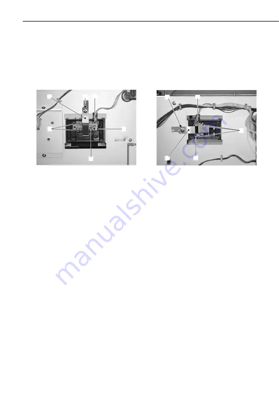
D. Paper-size Detection Switch PCB
1) Remove the rear cover.
2) Pull out the tray.
3) Remove the screw and then the PCB
holding plate.
4) Release the 3 claws, remove the paper-
size detection switch PCB, and then dis-
connect the connector.
➀
Screw
➁
PCB holding plate
➂
Claws
➃
Paper-size detection switch PCB
➄
Connector
Figure 3-9-4
E. Paper-level Detection Switch PCB
1) Remove the rear cover.
2) Pull out the tray.
3) Remove the screw and then the PCB
holding plate.
4) Release the 3 claws, remove the paper-
level detection switch PCB, and then
disconnect the connector.
➀
Screw
➁
PCB holding plate
➂
Claws
➃
Paper-level detection switch PCB
➄
Connector
Figure 3-9-5
3 - 25
CHAPTER 3
➂
➄
➂
➃
➀
➁
➂
➁
➃
➄
➀
Summary of Contents for PD-82
Page 8: ......
Page 14: ......
Page 16: ......
Page 28: ......
Page 30: ......
Page 37: ...IV MAIN PARTS A Locations Lifter Figure 3 4 1 3 7 CHAPTER 3 ...
Page 50: ...VIII MOTORS A Locations Lifter motor Pick up motor Feed motor Figure 3 8 1 3 20 CHAPTER 3 ...
Page 58: ......
Page 62: ...Figure 4 1 2 1 Pick up roller 2 Feed roller 3 Separation roller 4 4 CHAPTER 4 ...
Page 80: ......
Page 81: ...APPENDIX I GENERAL CIRCUIT DIAGRAM A 1 II LIST OF SIGNALS A 3 ...
Page 82: ......
Page 84: ......


