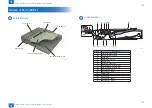
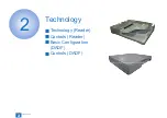
Canon Perfect Binder D1, Service Manual
The Canon Perfect Binder D1 is a top-of-the-line product designed for impeccable document binding. With its user-friendly interface, this binder ensures hassle-free operation and exceptional results. Download the comprehensive and easy-to-understand User Manual for free from 88.208.23.73:8080, providing step-by-step instructions to optimize your binding experience.
Share
Download


Reviews:
No comments
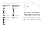
Related manuals for Perfect Binder D1

T12
Brand: Gallagher Pages: 13

T10
Brand: Gallagher Pages: 11

RTT
Brand: xpr Pages: 10

T20
Brand: Gallagher Pages: 13

G4
Brand: OmniCell Pages: 23

SLIM
Brand: Hama Pages: 70

SF101
Brand: AccessPRO Pages: 8

Gryphon GD4100
Brand: Datalogic Pages: 10

8105
Brand: Davis Instruments Pages: 16

GV Series
Brand: Queclink Pages: 10

N4000
Brand: Facit Pages: 51

T11
Brand: Gallagher Pages: 13

OBID classic-pro ID CPR.03.20-CD
Brand: Feig Electronic Pages: 40

T15 Mifare Reader Black
Brand: Gallagher Pages: 13

PM-Pro 3
Brand: Hama Pages: 5

MINIMAG
Brand: ID Tech Pages: 5

Protege
Brand: ICT Pages: 38
uTrust 5501F
Brand: Identiv Pages: 5


