background image

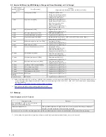
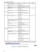
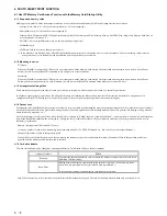
<Service mode operation procedures> 

1)  With the printer power turned off, while pressing the Resume/Cancel button, press and hold the Power button. (DO NOT release the buttons. The LED lights 

in green to indicate that a function is selectable.)


2)  While holding the Power button, release the Resume/Cancel button. (DO NOT release the Power button.)


3)  While holding the Power button, press the Resume/Cancel button 2 times, and then release both the Power and Resume/Cancel buttons. (Each time the 

Resume/Cancel button is pressed, the LED lights alternately in orange and green, starting with orange.)


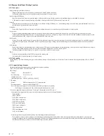
4)  When the LED lights in green, press the Resume/Cancel button the specified number of time(s) according to the function listed in the table below. (Each time 

the Resume/Cancel button is pressed, the LED lights alternately in orange and green, starting with orange.)


5)  After the function (menu) is selected, press the Power button. The LED lights in green, and the selected function is performed. (When the operation 

completes, the printer returns to the menu selection mode automatically.) 

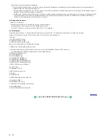
<Destination settings procedures> 

In the destination settings mode, press the Resume/Cancel button the specified number of time(s) according to the destination listed in the table below, and press 
the Power button. 


Note:  After setting the destination, confirm the model name in the service test print or EEPROM information print.  

[See 3-4. Verification Items, (1) Service test print,


or (2) EEPROM information print.]
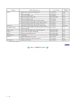
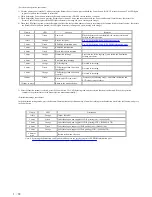


Time(s)

LED

Function

Remarks

0 times

Green

Power off


When the print head is not installed, the carriage returns and 
locks in the home position.


1 time

Orange

Service test print


See 3-4. Verification Items, (1) Service test print.


2 times

Green

EEPROM information print


See 3-4. Verification Items, (2) EEPROM information print.

3 times

Orange

EEPROM initialization


4 times

Green

Waste ink counter resetting


5 times

Orange

Destination settings


Proceed to the following step 5), and follow the Destination 
settings procedures.


6 times

Green

Print head deep cleaning


7 times

Orange

CD-R test print


Not used in servicing.


8 times

Green

CD-R print position correction 
(horizontal)


Not used in servicing.


9 times

Orange

CD-R print position correction 
(vertical)


Not used in servicing.


10 times 

Green

Button and LCD viewer test


 Proceed to the following step 5), and follow the Button and 
LCD viewer test


procedures.


11 times or more


Return to the menu selection


Time(s)

LED

Destination

1 time

Orange

Japan:  iP6100D


2 times

Green

Other than Japan, non-support of CD-R printing (A4):  iP6000D (A4)


3 times

Orange

Other than Japan, non-support of CD-R printing (LTR):  iP6000D (LTR) 


4 times

Green

Other than Japan, support of CD-R printing (A4):  iP6000D (A4)


5 times

Orange

Other than Japan, support of CD-R printing (LTR):  iP6000D (LTR) 


6 times or 

more


Return to the menu selection

1 - 14

Summary of Contents for PIXMA iP6000D

Page 1: ...ight 2004 Canon U S A This technical publication is the proprietary and confidential information of Canon U S A which shall be retained for reference purposes by Authorized Service Facilities of Canon U S A Its unauthorized use is prohibited ...

Page 2: ...PIXMA iP6000D SERVICE MANUAL Revision 0 QY8 13A6 000 COPYRIGHT 2004 CANON INC CANON PIXUS iP6100D PIXMA iP6000 082004 XX 0 00 0 ...

Page 3: ...l Canon will release technical information when necessary When substantial changes are made to the contents of the manual Canon will issue a revised edition The following do not apply if they do not conform to the laws and regulations of the region where the manual or product is used Trademarks Product and brand names appearing in this manual are registered trademarks or trademarks of the respecti...

Page 4: ...epair of the PIXMA iP6000D Part 2 Technical Reference New technology technical information and FAQ s Frequently Asked Questions etc of the PIXMA iP6000D Part 3 Appendix Block diagrams and pin layouts of the PIXMA iP6000D Reference This manual does not provide sufficient information for disassembly and reassembly procedures Refer to the illustrations in the separate Parts Catalog ...

Page 5: ...6 Service mode Service mode operation Destination settings Button and viewer test 3 4 Verification Items 1 Service test print 2 EEPROM information print 4 PRINTER TRANSPORTATION Part 2 TECHNICAL REFERENCE 1 NEW TECHNOLOGIES 2 CLEANING MODE AND AMOUNT OF INK PURGED 3 PRINT MODE 3 1 Resolution by Print Mode during Printing via Computer 3 2 Resolution in Borderless Printing 3 3 Resolution in Duplex P...

Page 6: ... Problems Specific to the iP6000D and Corrective Actions Part 3 APPENDIX 1 BLOCK DIAGRAM 2 CONNECTOR LOCATION AND PIN LAYOUT 2 1 Main Board 2 2 Print Beam Board 2 3 Card Slot Board 2 4 Operation Panel Board 2 5 Carriage Board Print Head Connector 3 PIXMA iP6000D SPECIFICATIONS 4 Print Media Specifications ...

Page 7: ...Part 1 MAINTENANCE ...

Page 8: ...rformed through service test print 2 min Print head alignment At print head replacement At logic board ass y replacement At carriage unit replacement To ensure accurate dot placement None operation panel Computer settings via the printer driver 2 min Paper feed motor position adjustment 1 At paper feed motor unit replacement To adjust the belt tension Position the paper feed motor so that the belt...

Page 9: ...No 5 plain paper standard mode BCI 6PM 260 pages ISO JIS SCID No 5 plain paper standard mode 1 4 Special Tools 1 5 Serial Number Location On the carriage flexible cable holder visible when the access cover is open To the top PIXMA iP6000D 5 000 pages Black 1 500 character pattern 1 500 pages Color A4 7 5 duty per color pattern 1 300 pages A4 30 duty per color pattern 400 pages 4 x 6 30 duty per co...

Page 10: ...2 Close the inner cover and press the Resume Cancel button CD R tray feeder closed during CD R printing 1850 1855 1 Open the CD R tray feeder set the CD R tray properly and press the Resume Cancel button CD R tray feder open during printing on paper 1851 1856 1 Close the CD R tray feeder and press the Resume Cancel button 7 times 1 No CD R or DVD R 1002 After setting a CD R or DVD R in the tray se...

Page 11: ...al temperature error 5400 Logic board ass y QM2 1786 1 7 times Waste ink absorber full 5B00 Ink absorber QC1 4221 4222 4223 4224 4257 4263 4264 4864 Bottom case unit QM2 1496 2 8 times Print head temperature rise error 5200 Print head QY6 0050 Logic board ass y QM2 1786 1 9 times EEPROM error 6800 Logic board ass y QM2 1786 1 11 times Carriage lift mechanism error 5110 Lift shaft QC1 4331 Photo in...

Page 12: ...lace the sheet feed unit or cassette Unsatisfactory print quality No printing or no color ejected Replace the ink tank print head 2 logic board ass y 1 or purge unit Printing is faint or white lines appear on printouts even after print head cleaning Line s not included in the print data appears on printouts Remove and re install the print head or replace the ink tank print head 2 purge unit or log...

Page 13: ...fter replacement 1 Initialize the EEPROM 2 Reset the waste ink counter 3 Set the destination in the EEPROM 4 Set the LCD viewer language 5 Correct the CD R and automatic print head alignment sensors See 3 3 Adjustment Settings 6 Service mode for details of 1 to 5 6 Perform the print head alignment in the user mode EEPROM information print Service test print Printing via parallel or USB connection ...

Page 14: ... and harness wiring connection Exercise care when handling the flexible cables and harness wiring Improper wiring or connection may cause a short circuit and may lead to ignition or emission of smoke I Logic board ass y and operation panel unit wiring 1 7 ...

Page 15: ... II DCC holder unit wiring III Paper feed motor side wiring To the top Part 1 3 REPAIR 3 2 1 8 ...

Page 16: ...est print and confirm that no strange noise or faulty print operation due to dislocation of the belt or gear or out of phase motor etc occurs Note The red screws securing the paper feed motor may be loosened only at replacement of the paper feed motor unit DO NOT loosen them in other cases 2 Gear phase adjustment In attaching the lift transmission gear QC1 4327 adjust the phase so that the protrus...

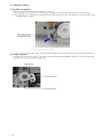
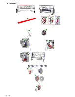
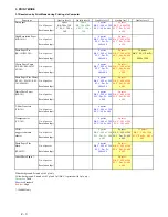
Page 17: ... 3 Grease application 1 10 ...

Page 18: ...e chassis FLOIL KG107A 1 drop Carriage shaft 9 Entire surface of the carriage shaft where the carriage unit slides FLOIL KG107A 200 to 400mg Carriage shaft spring L 10 Carriage shaft sliding portion over the area more than 2 3 from the top end of the spring FLOIL KG107A 1 drop Lift gear 2 shaft 11 Outer surface of the stepped portion where the spring slides MOLYKOTE HP300 1 drop Lift gear 2 12 Out...

Page 19: ...nual print head alignment On standalone printers press the Menu button to move to Maintenance and perform the selection Manual head align In Custom Settings of the printer driver s Maintenance sheet manual print head alignment by selecting the optimum values as with the conventional models can be performed Print head alignment values printing Print and confirm the print head alignment values set i...

Page 20: ... Function Procedures Remarks Service test print Model name ROM version USB serial number Waste ink amount CD R sensor correction LCD viewer language settings See Service mode operation procedures below Set a sheet of A4 or letter sized paper For a print sample see 3 4 Verification Items 1 Service test print Service test print sample EEPROM information print See Service mode operation procedures be...

Page 21: ...tination confirm the model name in the service test print or EEPROM information print See 3 4 Verification Items 1 Service test print or 2 EEPROM information print Time s LED Function Remarks 0 times Green Power off When the print head is not installed the carriage returns and locks in the home position 1 time Orange Service test print See 3 4 Verification Items 1 Service test print 2 times Green ...

Page 22: ...est 2 Press each button on the operation panel excluding the Power and Resume buttons Each time each button is pressed a part of the display will change to red The area changed to red is as shown in the diagram below The figure shows the display when both the Menu and OK buttons are pressed LCD viewer display 3 Press all buttons excluding the Power button and Resume button The entire LCD viewer wi...

Page 23: ...k items On the service test print sample below confirm the following items Check 1 nozzle check pattern Ink shall be ejected from all nozzles Check 2 top of form accuracy The line shall not extend off the paper Check 3 vertical straight lines The line shall not be broken Check 4 halftone There shall be no remarkable streaks or unevenness Check 5 CD R automatic print head alignment sensor correctio...

Page 24: ...0000 PR 00003 SP GP 00001 GP 00000 PC 00000 ENV 00000 23 UCPAGE All 00312 PP 00280 HR 00032 MP 00000 PR 00000 SP SG 00000 GP 00000 PC 00000 ENV 00000 24 BPPAGE All 00000 BSGP 000030 PC 00000 25 CDPAGE All 000 26 EDGE 00003 27 L 00004 28 CDR 00012 29 CDRP 00196 00283 30 CDRS 030 31 Head Temp 31 0 32 Env Temp 27 5 33 FF 07 80 00 34 OPP 00000 35 PrnB 00000 36 Seal 00000 37 CardPaper 00001 38 CardIns ...

Page 25: ...olution Paper Matte Photo Paper Photo Paper Pro Photo Paper Plus Glossy Photo Paper Plus Semi gloss Glossy Photo Paper Postcard Envelope 24 Auto duplex print pages total Photo Paper Plus Double Sided postcard 25 Camera Direct print pages total 26 Borderless print pages 27 L 4x6 print pages 28 Number of CD Rs printed 29 CD R print position adjustment 30 CD R sensor correction value 31 Print head te...

Page 26: ...w to prevent the fixing tool from caught into the inside of the printer ii Insert the fixing tool between the carriage and the main case unit and securely fix it with tape as shown in Figures B and C below Note The tape should be similar to the polyester tape used at shipment which will not easily be torn or removed or leave adhesive on the unit when removed Leave a sufficient length of tape to fi...

Page 27: ...Part 2 TECHNICAL REFERENCE ...

Page 28: ...ure For the following paper types and sizes automatic duplex printing can be performed Type Plain paper Super White Paper double sided plain paper Photo Paper Plus Double Sided double sided glossy photo paper Size A5 B5 5 x 7 A4 LTR 4 Card direct printing a By using a menu format GUI utilizing a newly adopted 2 5 inch built in LCD Viewer versus 2 0 inch for the i900D printing the desired output ca...

Page 29: ...aning after shipped from the plant 1 80 70 Dot count cleaning When the specified number of dots are printed since the previous cleaning Large and small nozzles for cyan and magenta counted separately 0 60 40 Timer cleaning 1 If 120 to 336 hours have elapsed since the previous cleaning till the start of the next printing Timer cleaning 2 If more than 336 hours have elapsed since the previous Black ...

Page 30: ...SG 101 KM No of passes Bk Y 600 x 1200 Bk Y 600 x 1200 101 MM 101 Resolution dpi M C Pm Pc 600x 600 M C Pm Pc 600 x 600 Matte Photo Paper 6 passes 8 passes MP 101 No of passes Bk Y 600 x 1200 Bk Y 600 x 1200 Resolution dpi M C Pm Pc 600 x 600 M C Pm Pc 600 x 600 T Shirt Transfers 6 passes TR 301 No of passes Bk Y 600 x 1200 Resolution dpi M C 600 x 600 Transparencies 6 passes 8 passes CF 102 No of...

Page 31: ... C Pm Pc 600x600 Matte Photo Paper No of passes 6 passes 8 passes MP 101 Resolution dpi Bk Y 600 x 1200 Bk Y 600 x 1200 M C Pm Pc 600 x 600 M C Pm Pc 00 x 600 Photo Paper Plus No of passes 6 passes 8 passes Doble Sided Resolution dpi Bk Y 600 x 1200 Bk Y 600 x 1200 PP 101D M C Pm Pc 600 x 600 M C Pm Pc 600 x600 Other Photo Paper No of passes 8 passes Resolution dpi Bk Y 600 x 1200 M C Pm Pc 600 x ...

Page 32: ... KM 101 MM 101 Resolution dpi Bk Y 600 x 1200 Bk Y 600 x 1200 M C Pm Pc 600 x 600 M C Pm Pc 600 x 600 Photo Paper Plus Glossy No of passes 8 passes 8 passes PP 101 SG 101 KM 101 MM 101 Resolution dpi Bk Y 600 x 1200 Bk Y 600 x 1200 GP 401 EC 101 KH 201N M C Pm Pc 600 x 600 M C Pm Pc 600 x 600 Matte Photo Paper No of passes 6 passes 8 passes MP 101 HR 101S Resolution dpi Bk Y 600 x 1200 Bk Y 600 x ...

Page 33: ...h the latter 4 being numeric in compliance with the DCF Design rule for Camera File system Files are sorted in ascending order of those 4 numeric figures 4 1 4 Data access For mounted cards in the iP6000D data access to the memory card is possible by performing the usual file operations through the OS s standard file control software such as Explorer and Finder and general software applications Th...

Page 34: ...le printing it is not possible to specify the number of copies to print After sample printing select a favorite color tone number displayed on UI of LCD and print it In printing images other than samples it is possible to specify the number of copies to print DPOF Performs printing according to the DPOF settings in the memory card It is not possible to specify the number of copies to print 4 2 2 P...

Page 35: ...nd directory name Extension 3 characters 4 character extensions JPEG TIFF are not supported 4 3 File Search In the following explanation O indicates files and directories to be searched and X indicates files and directories excluded from searching Images to be searched are jpg and tif files within the 4th or less layer directories including root O xxx jpg O DCIM 110CANON xxx jpg O ABCD EFGH IJKL x...

Page 36: ...ected sorting by distance in ascending order eg IMG001 JPG IMG_001 JPG C 2 When the result of the comparison in C 1 above is the same numbers are sorted in ascending order eg IMG001 JPG ABC002 JPG C 3 When the result of the comparison in C 2 above is the same the length of the numerical string is sorted in ascending order eg IMG001 JPG ABC0001 JPG The length of the former is 3 and the latter is 4 ...

Page 37: ...of Memory Card Direct Printing 4 6 4 Print quality No of passes 8 passes Resolution Bk Y M C PM PC 4 800 dpi x 1 200 dpi Bk Y 5 pl M C PM PC 5 pl 2 pl mixed 4 6 5 Image correction function Exif 2 2 files are processed with APP Auto Photo Perfect and for other files image correction is not implemented Not selectable by users 4 6 6 Maintenance Maintenance operation of the iP6000D via the digital cam...

Page 38: ... 2 1 standard 1 2 Contrast 2 1 standard 1 2 Color hue Skin color red 2 red 1 non adjustment yellow 1 yellow 2 4 7 7 Image processing Sepia Simulate illustration Non processing 4 7 8 Maintenance Maintenance operation of the iP6000D via the digital camera s operation panel is not possible Maintenance operations are possible through the operation panel of the iP6000D printer even when connected to th...

Page 39: ... slot for SM MS and SD MMC used in common however multiple cards can not be inserted simultaneously and a slot for a CF card However even though a CF card and other card are inserted simultaneously as one drive only is always valid control are performed as follows The card inserted first has priority Even if a card is inserted into a drive other than the current drive this action is ignored When t...

Page 40: ...vents occurs the memory card detection process starts and if an accessible memory card is recognized power supply to the memory card starts The Access lamp lights a When a memory card is inserted into the card slot while the printer is on b When the printer is powered on while a memory card is in the card slot c When the USB bus is reset while the printer is on with a memory card in the card slot ...

Page 41: ...es designated for Standard printing in the DPOF file are printed in the designated order in the layout designated through the operation panel Images designated for index printing will be printed using the printer s index layout regardless of the specified layout No of copies to be printed The number of copies cannot be designated from the operation panel Only the number of copies designated in the...

Page 42: ...Japanese Media types for overseas are common for all markets however the panel display differs depending on the languages The following is the display of US English Index printing LTR A4 80 photos 4 x 6 24 photos 5 x 7 35 photos Single frame printing A4 LTR with borderless bordered 4 x 6 with borderless bordered 5 x 7 with borderless bordered When the language setting on the digital camera is set ...

Page 43: ...lly divided between top and bottom or left and right Note As printing of the image is performed to an area 5 mm larger than that of the paper size the perimeter of the image is further trimmed by a few millimeters Processing in printing in print area without image trimming 1 Rotate the image data by 90 degrees if necessary to align the long edge of the image data with that of the paper 2 Enlarge o...

Page 44: ...ce from the lower right to the image date is the same as when a 4 3 ratio is used Color Orange Size According to the layout 4 13 2 Date print in Digital Camera Direct Printing 1 Settings and data format When date print is set in the digital camera the date is printed using the character strings sent by the digital camera However in Bubble Jet Direct index printing using the digital camera the date...

Page 45: ...g Printing in other modes The photo number will not be printed 4 14 2 Photo number printing in Digital Camera Direct Printing 1 Data format The photo number will not be printed even when set in the DPOF settings a 2 Print location color and size The photo number will not be printed To the top Printing in Index mode Location Below the image Above the date Color Black Size Fixed size Index mode Inde...

Page 46: ...portation for return after repair Ink dries and no ink is ejected 6 A Print results Soiling on the back side of paper lines or streaks parallel to the paper feed direction After continuous borderless printing of small sized paper such as 4 x 6 when a larger sized paper such as A4 is printed With Photo Paper Plus Double Sided or postcards the phenomenon is likely to be noticeable and to be complain...

Page 47: ...feeding method from the cassette to the sheet feeder If automatic duplex printing is performed cancel it and by setting only a single sheet of paper in the auto sheet feeder manually print each side of paper Scratches on the PF return lever due to paper feeding from the cassette and duplex printing path 9 B Print results Soiling on the print surface of a page PSHR KM 101 PR 101 L 4 x 6 Paper is cu...

Page 48: ...er off AC 110 to 120 V 50 60Hz Approx 15 W Approx 3 W Approx 1 W AC 220 to 240 V 50 60Hz Approx 15 W Approx 3 W Approx 1 W External dimensions Printer With the paper support and output tray retracted Approx 429 W x 312 D x 195 H mm With the paper support and output tray extended Approx 429 W x 548 D x 323 H mm Weight Approx 7 0 kg not including print head and optional units Related standards Propo...

Page 49: ... from a 3 mega pixel digital camera Process from pressing the printing start button to ejecting paper Direct camera print function Supported digital cameras Digital cameras and digital video cameras supporting Bubble Jet Direct or PictBridge Supported print paper See 3 4 Print Media Specifications Print layout 1 paper bordered borderless Index printing 2 4 9 16 images bordered Resolution Max 1 200...

Page 50: ... A4 LTR ASF Cassette 10 sheets Yes Yes Yes PR 101 4x6 101 6 x 152 4 mm ASF Cassette 20 sheets Yes Yes Yes Photo Paper Plus Glossy PP 101 A4 LTR ASF Cassette 10 sheets Yes Yes Yes PP 101 4x6 101 6 x 152 4 mm ASF Cassette 20 sheets Yes Yes Yes PP 101 5x7 127 x 178 mm ASF Cassette 10 sheets Yes Yes Yes Matte Photo Paper MP 101 A4 LTR ASF Cassette 10 sheets Yes Yes Photo Paper Plus Semi gloss SG 101 A...

Reviews: