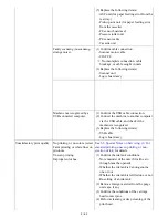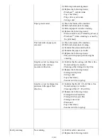
from stain or damage. When returning the strap, make
sure of its orientation (left and right, front and back).
- See
2-2. Disassembly & Reassembly Procedures, (7)
Carriage unit removal
, for details.
in Service Mode
, for details.]
In the user mode:
3. Perform automatic print head
alignment.
Switch
system unit
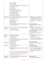
(1) to (10) Same as for the absorber kit procedures.
(11) PE sensor board ass'y
(12) ASF unit
(13) Logic board ass'y
(14) Right chassis
(15) Front chassis
(16) Main chassis (together with the carriage unit and
pressure roller ass'y)
(17) Spur unit
(18) Platen unit
(19) Cassette feed roller unit
(20) Duplex paper feed roller unit
(21) Cassette feed guide
(22) Paper guide unit
(23) Paper feed roller unit
(24) Switch system unit or paper feed motor
- The screws securing the paper feed motor are allowed
to be loosened only for paper feed motor replacement.
(DO NOT loosen them in any other cases.)
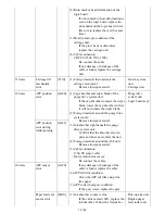
1. Adjust the paper feed motor.
[See
3-5. Special Notes on
Servicing, (2) Paper feed motor
adjustment
, for details.]
In the service mode:
2. Print the integrated inspection
pattern.
Paper feed
motor
Platen unit
(1) to (10) Same as for the absorber kit procedures.
(11) PE sensor board ass'y
(12) ASF unit
(13) Logic board ass'y
(14) Right chassis
(15) Front chassis
(16) Main chassis (together with the carriage unit)
(17) Spur unit
(18) Platen unit
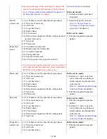
In the service mode:
1. Perform LF / Eject correction
(only when uneven printing or
streaks appear on printouts after
replacement).
[See
3-3. Adjustment and Settings
in Service Mode
, for details.]
2. Print the integrated inspection
pattern.
Spur unit
(1) to (10) Same as for the absorber kit procedures.
(11) PE sensor board ass'y
(12) ASF unit
(13) Logic board ass'y
(14) Right chassis
(15) Front chassis
(16) Main chassis (together with the carriage unit)
(17) Spur unit
In the service mode:
1. Print the integrated inspection
pattern.
2. Perform LF / Eject correction
(only when uneven printing or
streaks appear on printouts after
replacement).
[See
3-3. Adjustment and Settings
in Service Mode
, for details.]
Purge drive
system unit
(1) to (10) Same as for the absorber kit procedures.
(11) PE sensor board ass'y
(12) ASF unit
(13) Logic board ass'y
In the service mode:
1. Print the integrated inspection
pattern.
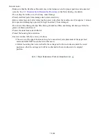
16 / 62
Summary of Contents for PIXMA MG5220 Series
Page 29: ...8 Remove the scanner unit Disconnect two harnesses and one FFC Remove one core 25 62 ...
Page 55: ...51 62 ...
Page 60: ...4 2 Integrated Inspection Pattern Print Print sample 56 62 ...
Page 61: ...4 3 Ink Absorber Counter Value Print Print sample 4 VERIFICATION AFTER REPAIR 57 62 ...
Page 64: ...60 62 ...

