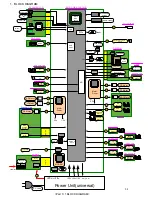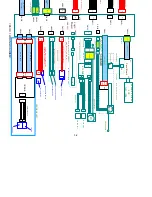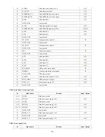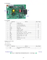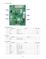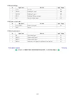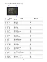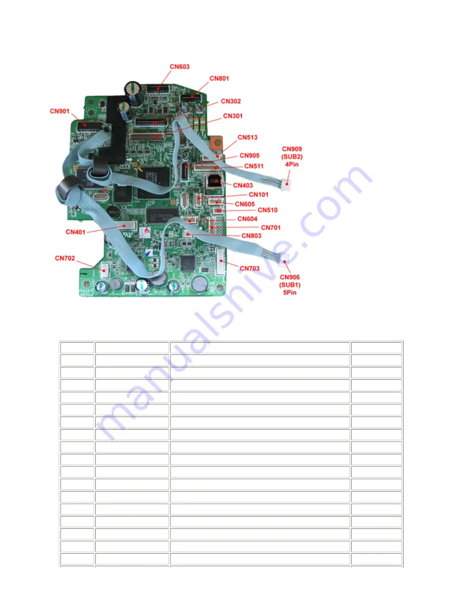
3. CONNECTOR LOCATION AND PIN LAYOUT
3-1. Logic Board Ass'y
CN101 (Not used)
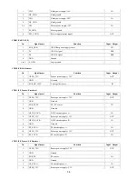
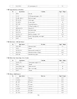
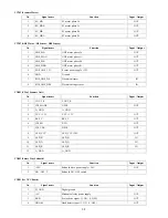
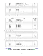
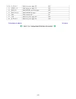
CN301(Print Head 1/2 [Carriage Unit])
No.
Signal name
Function
Input / Output
1
AB_POW
Ink tank sensor chip power supply
OUT
2
AB_DATA
Ink tank sensor data signal
BUS
3
AB_POW
Ink tank sensor chip power supply
OUT
4
AB_CLK
Ink tank sensor data transfer clock signal
BUS
5
LOGIC_GND
Logic ground
-
6
H_D3
Head data (PK2)
OUT
7
H_D0
Head data (BK1)
OUT
8
H_D1
Head data (BK2)
OUT
9
H_D5
Head data (SC1)
OUT
10
H_ENB0
Head heat enable signal 0 (BK)
OUT
11
LOGIC_GND
Logic ground
-
12
DIA0
Diode sensor anode 0
IN
13
LOGIC_GND
Logic ground
-
14
H_D2
Head data (PK1)
OUT
15
H_D4
Head data (C1)
OUT
16
H_ENB3
Head heat enable signal (SCol)
OUT
17
H_D8
Head data (Y1)
OUT
3-3
Summary of Contents for PIXMA MP530
Page 5: ...Part 1 MAINTENANCE ...
Page 34: ... Right side c Disconnect the connector for the solenoid 1 29 ...
Page 51: ... Service test print sample 1 46 ...
Page 56: ... System data list sample 1 51 ...
Page 57: ... Error transmission report sample 1 52 ...
Page 60: ...Part 2 TECHNICAL REFERENCE ...
Page 73: ...Part 3 APPENDIX ...


