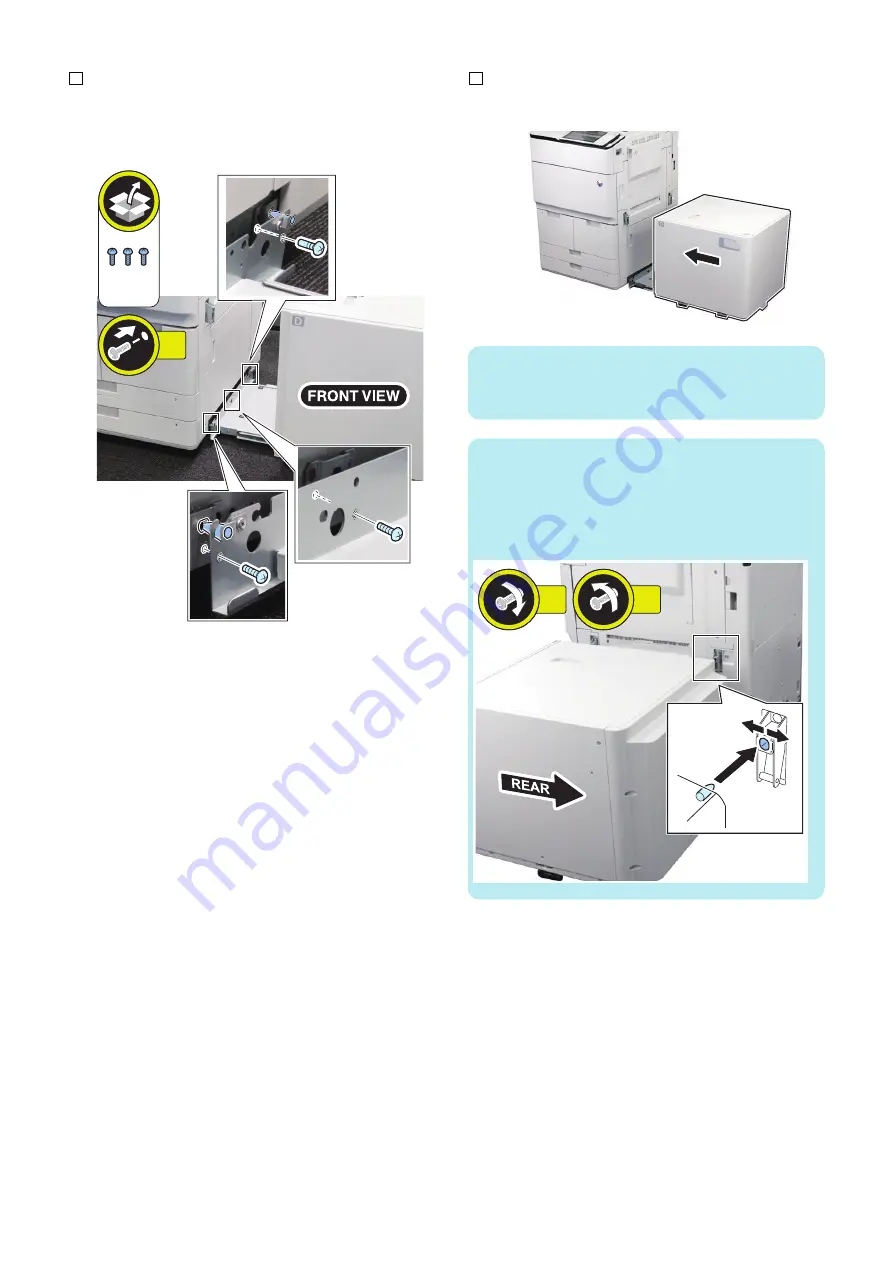
9. Insert the 2 positioning pins to the holes of the host
machine and then fix the base stay.
• 3 Screws (Binding screws; M4x5)
3x
Binding
M4x5
10. Connect the POD Deck Lite with the host machine.
NOTE:
• Do not nip the cable between the POD Deck Lite and
the host machine when connecting.
NOTE:
• When inserting the rear connection pin into the rear
latch hole is difficult, loosen the 2 screws fixing the
latch plate and then adjust the position of the latch
plate to fit it in. Check that the latch plate is not
positioned at an angle when installing.
2x
2x
6. Installation
113
Summary of Contents for POD Deck Lite-C1
Page 1: ...Revision 2 0 POD Deck Lite C1 Service Manual ...
Page 10: ...Product Overview 1 Features 5 Specifications 6 Names of Parts 7 Option Construction 10 ...
Page 17: ...Technology 2 Basic Configuration 12 Controls 15 Upgrading 26 ...
Page 33: ...Periodical Service 3 List of Work for Scheduled Servicing 28 ...
Page 37: ...6 Remove the base stay unit 3 Screws 3x 4 Disassembly Assembly 31 ...
Page 52: ... Procedure 1 Remove the Upper Cover 5 Screws 5x 4 Disassembly Assembly 46 ...
Page 69: ...5 Remove the Air Heater from rear of the Compartment 2 Screws 2x 4 Disassembly Assembly 63 ...
Page 72: ...2 Remove the Deck Pickup Release Solenoid 2 Screws 2x 4 Disassembly Assembly 66 ...
Page 93: ...Adjustment 5 Adjustment 88 Actions when Replacing the Parts 90 Other Adjustment 96 ...
Page 150: ...APPENDICES Service Tools 145 General Circuit Diagram 146 ...


