Introduction
Important Notices
Application
This manual has been issued by Canon Inc. for qualified persons to learn technical theory, installation, maintenance, and repair
of products.
This manual covers all localities where the products are sold. For this reason, there may be information in this manual that does
not apply to your locality.
Corrections
This manual may contain technical inaccuracies or typographical errors due to improvements or changes in products.
When changes occur in applicable products or in the contents of this manual, Canon will release technical information as the
need arises. In the event of major changes in the contents of this manual over a long or short period, Canon will issue a new
edition of this manual.
The following paragraph does not apply to any countries where such provisions are inconsistent with local law.
Trademarks
The product names and company names used in this manual are the registered trademarks of the individual companies.
Copyright
This manual is copyrighted with all rights reserved. Under the copyright laws, this manual may not be copied, reproduced or
translated into another language, in whole or in part, without the consent of Canon Inc.
Copyright CANON INC. 2015
Caution
Use of this manual should be strictly supervised to avoid disclosure of confidential information.
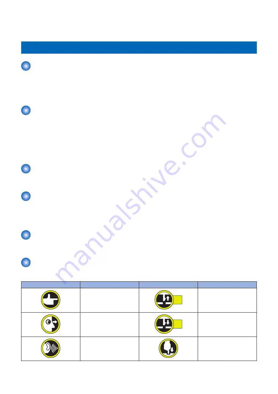
Explanation of Symbols
The following symbols are used throughout this Service Manual.
Symbols
Explanation
Symbols
Explanation
Check.
1x
Remove the claw.
Check visually.
1x
Insert the claw.
Check a sound.
Push the part.
Introduction
Summary of Contents for POD Deck Lite-C1
Page 1: ...Revision 2 0 POD Deck Lite C1 Service Manual ...
Page 10: ...Product Overview 1 Features 5 Specifications 6 Names of Parts 7 Option Construction 10 ...
Page 17: ...Technology 2 Basic Configuration 12 Controls 15 Upgrading 26 ...
Page 33: ...Periodical Service 3 List of Work for Scheduled Servicing 28 ...
Page 37: ...6 Remove the base stay unit 3 Screws 3x 4 Disassembly Assembly 31 ...
Page 52: ... Procedure 1 Remove the Upper Cover 5 Screws 5x 4 Disassembly Assembly 46 ...
Page 69: ...5 Remove the Air Heater from rear of the Compartment 2 Screws 2x 4 Disassembly Assembly 63 ...
Page 72: ...2 Remove the Deck Pickup Release Solenoid 2 Screws 2x 4 Disassembly Assembly 66 ...
Page 93: ...Adjustment 5 Adjustment 88 Actions when Replacing the Parts 90 Other Adjustment 96 ...
Page 150: ...APPENDICES Service Tools 145 General Circuit Diagram 146 ...


