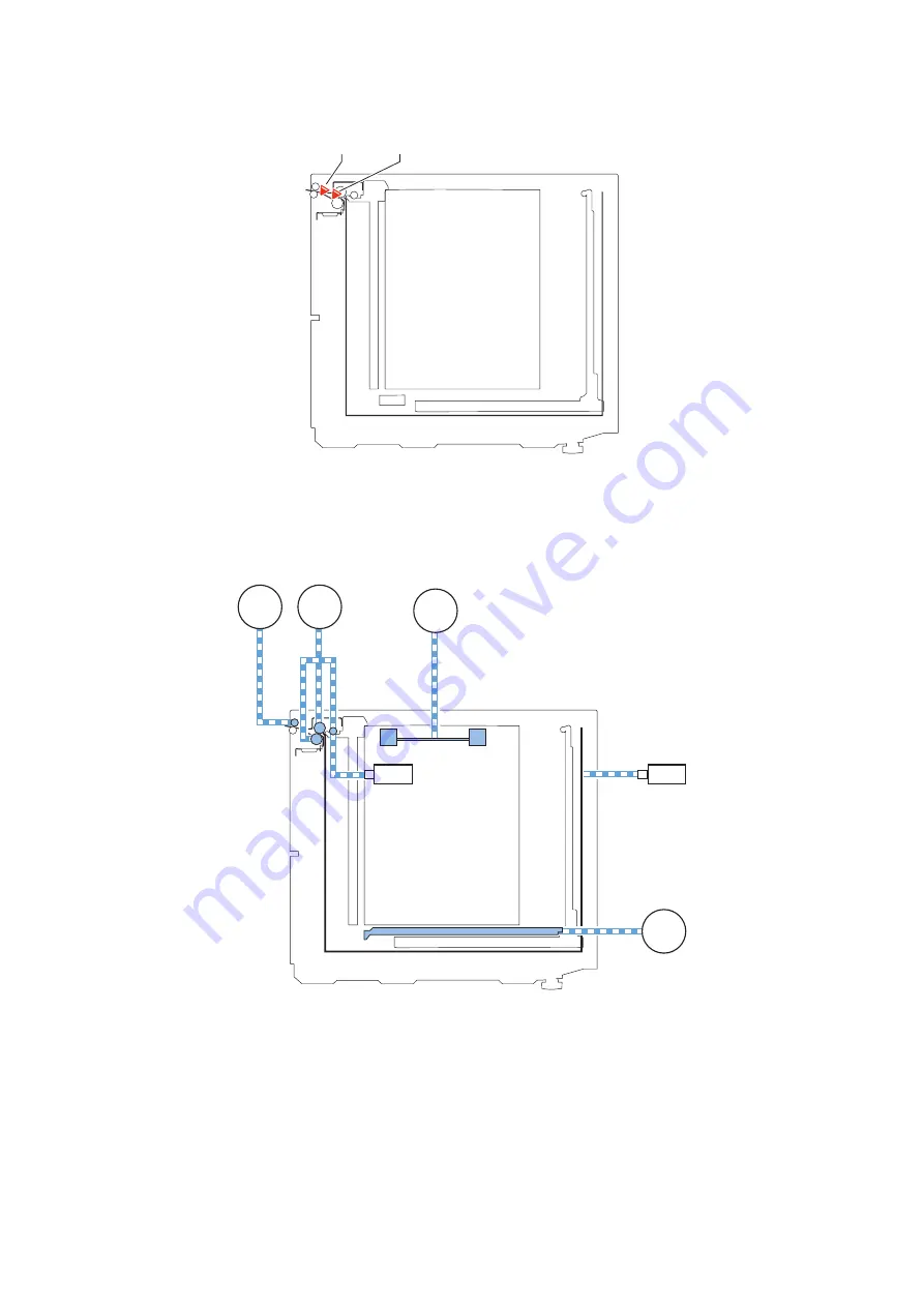
■ Sensor Layout
Only the optical sensors on the feed path are shown below.
SR6
SR7
SR6
Deck pull-out sensor
SR7
Deck pickup sensor
■ Drive Configuration
M2
SL2
M1
M4
M3
SL1
M1
Deck pickup motor
M2
Deck pull-out motor
M3
Deck lifter motor
M4
Swing motor
SL1
Compartment open solenoid
SL2
Deck pickup release solenoid
2. Technology
14
Summary of Contents for POD Deck Lite-C1
Page 1: ...Revision 2 0 POD Deck Lite C1 Service Manual ...
Page 10: ...Product Overview 1 Features 5 Specifications 6 Names of Parts 7 Option Construction 10 ...
Page 17: ...Technology 2 Basic Configuration 12 Controls 15 Upgrading 26 ...
Page 33: ...Periodical Service 3 List of Work for Scheduled Servicing 28 ...
Page 37: ...6 Remove the base stay unit 3 Screws 3x 4 Disassembly Assembly 31 ...
Page 52: ... Procedure 1 Remove the Upper Cover 5 Screws 5x 4 Disassembly Assembly 46 ...
Page 69: ...5 Remove the Air Heater from rear of the Compartment 2 Screws 2x 4 Disassembly Assembly 63 ...
Page 72: ...2 Remove the Deck Pickup Release Solenoid 2 Screws 2x 4 Disassembly Assembly 66 ...
Page 93: ...Adjustment 5 Adjustment 88 Actions when Replacing the Parts 90 Other Adjustment 96 ...
Page 150: ...APPENDICES Service Tools 145 General Circuit Diagram 146 ...


