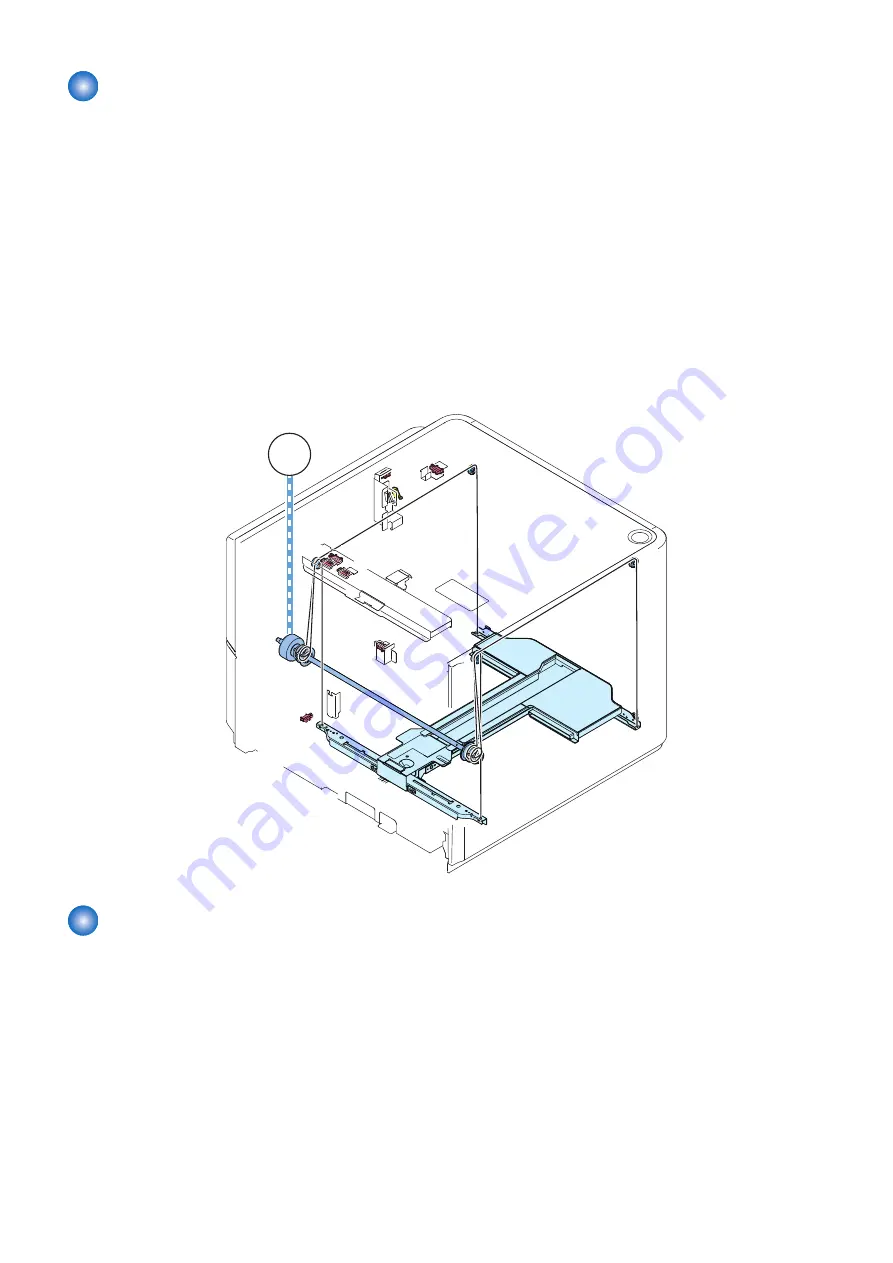
Lifter Control
■ Moving Up the Lifter
The lifter starts to move up when the compartment open/close switch (SW4) and the compartment open/close sensor (SR9)
detect that the compartment has been set in place.The lifter then stops when the paper level sensor (SR3) detects the top surface
of the stack of paper placed on the lifter.The deck lifter upper limit sensor 1/2 (SR4/5) is used to prevent damage otherwise caused
by the failure of the lifter to stop after the sensor lever blocks the paper level sensor (SR3).The machine is also equipped with a
protective mechanism by means of an obstacle sensor (SR8) used to prevent damage to the lifter cable and resin gears lest a
foreign object inside the compartment should hit the ceiling before the paper level sensor (SR3) detects the top surface of the
stack of paper.
■ Moving Down the Lifter
The lifter starts to move down when the compartment open switch is pushed until the lifter passes through the sensor lever of
the relay paper sensor (SR2). When paper is supplied in this condition, the lifter moves down to the position where the paper
passes through the sensor lever as the paper pushes the sensor lever. The lifter keeps moving down until the lifter passes through
the deck lifter lower position sensor (SR13) which detects maximum paper supply position each time when paper is supplied.
SR13
SW4
SR9
SR2
SR3
SR4
SR5
SR8
M3
Remaining Paper Level Detection Control
The level of the paper remaining is detected by counting the pulses of the encoder for the lifter motor rotation sensor (SR14) that
represent the distance of movement of paper from the deck lifter lower position sensor (SR13) to the paper level sensor (SR3).The
encoder for the lifter motor rotation sensor (SR14) rotates in synchronization with the deck lifter motor (M3).When the relay paper
sensor (SR2) became OFF from ON during paper feed, the count value of the pulse is reset for the correction of the detection
error by the wire growth.The lifter position information is memorized in the EEPROM of the deck driver PCB. Therefore the lifter
position control is not performed after sleep again.The level of the paper remaining is indicated on the display on the host machine.
2. Technology
17
Summary of Contents for POD Deck Lite-C1
Page 1: ...Revision 2 0 POD Deck Lite C1 Service Manual ...
Page 10: ...Product Overview 1 Features 5 Specifications 6 Names of Parts 7 Option Construction 10 ...
Page 17: ...Technology 2 Basic Configuration 12 Controls 15 Upgrading 26 ...
Page 33: ...Periodical Service 3 List of Work for Scheduled Servicing 28 ...
Page 37: ...6 Remove the base stay unit 3 Screws 3x 4 Disassembly Assembly 31 ...
Page 52: ... Procedure 1 Remove the Upper Cover 5 Screws 5x 4 Disassembly Assembly 46 ...
Page 69: ...5 Remove the Air Heater from rear of the Compartment 2 Screws 2x 4 Disassembly Assembly 63 ...
Page 72: ...2 Remove the Deck Pickup Release Solenoid 2 Screws 2x 4 Disassembly Assembly 66 ...
Page 93: ...Adjustment 5 Adjustment 88 Actions when Replacing the Parts 90 Other Adjustment 96 ...
Page 150: ...APPENDICES Service Tools 145 General Circuit Diagram 146 ...


