Chapter 3
3-9
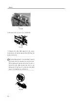
F-3-30
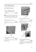
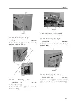
9) Disconnect the connector [1] of the horizontal
registration motor and the connector [2] of the
horizontal registration home position sensor, and
remove the punch unit harness.
F-3-31
3.3.1.6
Installing the Punch
Unit Harness
0003-6806
Offset punch unit harnesses can cause
malfunction. The punch unit harnesses must be
firmly installed at the positions described below.
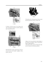
1) Fasten the punch unit harnesses so that the two tie
wraps [1] of the punch unit harnesses are on the
outside of the two respective clamps [2].
F-3-32
F-3-33
3.3.2
LED PCB
3.3.2.1
Removing the Rear
Cover
0003-6809
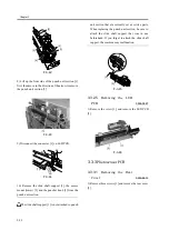
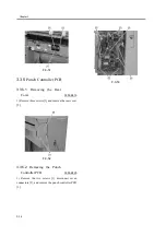
1) Remove three screws [1] and remove the rear cover
[2].
[1]
[1]
PI62
PI63
M61
PI61
M62
LED PCB
Potosensor
PCB
Punch Controller
PCB
Summary of Contents for Puncher Unit-L1
Page 1: ...Feb 21 2005 Service Manual Finisher Sorter DeliveryTray Puncher Unit P1 ...
Page 2: ......
Page 6: ......
Page 10: ......
Page 11: ...Chapter 1 Specifications ...
Page 12: ......
Page 14: ......
Page 19: ...Chapter 2 Functions ...
Page 20: ......
Page 22: ......
Page 34: ......
Page 35: ...Chapter 3 Parts Replacement Procedure ...
Page 36: ......
Page 53: ...Chapter 4 Maintenance ...
Page 54: ......
Page 56: ......
Page 76: ...4 Mount the rear cover to the Puncher 5 Turn on the power of the host machine ...
Page 78: ......
Page 79: ...Chapter 5 Error Code ...
Page 80: ......
Page 82: ......
Page 87: ...Chapter 5 5 5 5 3 5 E592 0003 8767 ...
Page 88: ...T 5 7 ...
Page 91: ...Feb 21 2005 ...
Page 92: ......


