background image

4

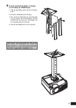
Installatie aan een vlak en horizontaal plafond

Montage en installatie

Voorbereiding:

Haal de verbindingskoppeling tijdelijk 

los van de plafondbevestigingsplaat  

Verwijder vier M5 schroeven om de verbin-

dingskoppeling van de plafondbevestigings-

plaat te kunnen halen. 

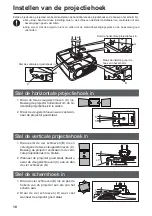
1


Maak een gat in het plafond

Maak een gat in het plafond voor de pla-

fondbevestigingsplaat en de bedrading. 

● Gebruik  het  meegeleverde  sjabloon  om  de 

plaats van het gat te bepalen.

● De richting van het scherm staat aangegeven 

op het sjabloon.

2


Bevestig de plafondbevestigingsplaat 

aan het plafond

Gebruik vier M13 schroeven om de pla-

fondbevestigingsplaat aan het plafond te 

bevestigen met de pijl in de richting van het 

scherm.

● Vergeet niet het sjabloon weg te halen voor u de 

plafondbevestigingsplaat vast zet. 

● De M13 schroeven worden niet meegeleverd 

met de plafondbevestiging. Zorg zelf voor M13 

schroeven die geschikt zijn voor het materiaal 

en de constructiewijze van het plafond.  

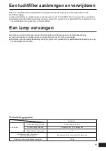
3


Bevestig de basisplaat aan de pro-

jector

Gebruik  hiervoor  de  meegeleverde  M4 

schroeven (6 stuks).

Richting scherm

Richting scherm

Summary of Contents for RS-CL11

Page 1: ... attacco per soffitto Plafondbevestiging 組立 設置説明書 Assembly Installation Manual Manuel d assemblage installation Manual de instalación Zusammenbau und Installationsanleitung Manuale per l installazione montaggio Handleiding voor montage en installatie RS CL11 JPN ENG FRA SPA GER ITA NLD ...

Page 2: ...止事項 を示してい ます 注意 この記号は 必ず守っていただきたい行為や内容を示しています 警告 設置および取り扱い上 以下の点にご注意ください 火災や感電またはケガの原因になります 注意 取り付け作業は足場の安全を確保してから行ってください プロジェクターの電源プラグやコネクターは 根元まで確実に差し込んでください また 痛んだプラグや ゆるんだコンセントは使用しないでください 禁止 天吊り金具のネジは確実に締め ゆるめたり取り外したりしないでください プロジェクターの投写の調整中は強い光が出ていますので レンズをのぞかない でください 目を傷める恐れがあります 注意 設置および取り扱い上 以下の点にご注意ください 禁止 設置工事は必ず専門業者の技術者または販売店に依頼してください 工事の不 備により 事故の原因となることがあります プロジェクターの動作中に レンズの前に物をおかないでく...

Page 3: ...バー M5 ねじ 12 mm 4 本 M3 ねじ 10 mm 1 本 延長量は 55 95 cm で 5 cm ごとに調整できます RS CL08 外側 内側パイプ 外側 内側カバー M5 ねじ 12 mm 4 本 M3 ねじ 10 mm 1 本 延長量は 35 55 cm で 5 cm ごとに調整できます 天井取り付け金具 連結金具 2 2 2 4 4 4 6 天吊り金具 Ceiling Attachment Fixation pour plafond Soporte de techo Deckenhalterung Dell attacco per soffitto Plafondbevestiging 組立 設置説明書 Assembly Installation Manual Manuel d assemblage installation Manual de instalación...

Page 4: ...用いて組立 設置の説明をしています プロジェクターはスクリーンの正面に設置してください ただし レンズシフトを使って画面の位置 ひずみを 補正することができます 詳しくはプロジェクターの使用説明書をご覧ください 194 mm 236 mm 430 mm 380 mm 92 mm 209 mm 91 mm 194 mm 236 mm 80mm 183 mm 92 mm 167 mm 167 mm 190 mm 190 mm RS CL11 投写距離 H1 高さ H2 高さ 側面図 正面図 上面図 100 mm 100 mm 80 mm 80 mm 100 mm 100 mm 80 mm 80 mm 天井取り付け金具 注意 天井からレンズ中心までの距離 ℓ RS CL11 RS CL08を使用 RS CL09を使用 21 cm 56 76 cm 76 116 cm 画面サイズ H1 H2 と投...

Page 5: ...します 1 天井に穴を開ける 天井取り付け金具の固定用とケーブル類の 配線用の穴を開けます 穴の位置を決めるときは 付属のテンプレー ト紙をご使用ください テンプレート紙にはスクリーンの方向が記載 されています スクリーン方向 スクリーン方向 2 天井取り付け金具を天井に固定する 金具の矢印をスクリーンに向け M13 ね じ 4 本で天井に固定します 金具の取り付け前にテンプレート紙ははがし てください M13 ねじは同梱していません 天井の構造に 適したねじをご用意ください 3 本体取り付け金具をプロジェクターに 固定する 付属の M4 ねじ 6 本 をご使用ください ...

Page 6: ... B のねじに通します 調整脚をプロジェクターに取り付け 落 下防止ワイヤーを固定します 同様に もう一方の調整脚にもワッシャー と落下防止ワイヤーを取り付けます 調整脚は 緩みのないようにしっかり締め 付け固定してください 調整脚のねじに M8 ナットを取り付けると きは スパナなどの工具を使用しないでく ださい 落下防止ワイヤーは必ず 2 本とも取り付け てください セキュリティーバーは プロジェクターの設 置作業の落下防止としてもご使用ください スクリーン方向 ワッシャー M8 ナット ワイヤー セキュリティーバー B A 5 天井の穴からケーブル類を出す 6 天井取り付け金具に連結金具を固定する 準備のときに外した M5 ねじ 4 本で固定し ます ...

Page 7: ...6 7 本体取り付け金具を連結金具に掛けて 仮止めする 連結金具の突起 A に引っ掛け 付属の M5 ねじ B 4 本で仮止めします 図のようにケーブル類を引き出してください ねじ B は 投写角度の調整 P 10 の後でしっ かり締めて固定してください 8 ケーブル類を接続する プロジェクターにケーブル類を接続しま す B A B 設置が終わったら 投写角度を調 整してください P 10 ...

Page 8: ...の延長用パイプRS CL08またはRS CL09を使用します 取り付け穴の位置 天井からレンズ光軸までの距離 ℓ RS CL08 RS CL09 a 56 cm 76 cm b 61 cm 81 cm c 66 cm 86 cm d 71 cm 91 cm e 76 cm 96 cm f 101 cm g 106 cm h 111 cm i 116 cm パイプの延長量 イメージシフトがデフォルトのとき f a b c e d h ℓ i ℓ 延長用パイプを最長の長さで使用する場合は 連続した 2 穴で固定してください ℓ 9cm 1 天井取り付け金具と連結金具をいった ん分離する P 4 準備 2 天井に穴を開ける P 4 手順 1 3 天井取り付け金具を天井に固定する P 4 手順 2 4 本体取り付け金具をプロジェクターに 固定する P 4 手順 3 5 落下防止ワイヤーを取り付ける...

Page 9: ...パイプの開放部は天井取り付け金具 の開放部に対して 180 度になる向きで取り付 けます スクリーン方向 7 連結金具を延長パイプの下端に取り付 ける 準備のときに天井取り付け金具から外して おいた M5 ねじ 4 本で固定します スクリーン方向 スクリーン方向 B A B 8 本体取り付け金具を連結金具に掛けて 仮止めする 連 結 金 具 の 突 起 A に 引 っ 掛 け 付 属 の M5 ね じ B 4 本 で 仮 止 め し ま す ねじ B は 投写角度の調整 P 10 の後 でしっかり締めて固定してください ...

Page 10: ...9 9 ケーブル類をパイプ内に配線し カ バーを閉める 天井の穴からケーブル類を引き出します パイプの内側にケーブル類を収納します パイプのカバーを内側 外側の順で閉め 延長用パイプに付属の M3 ねじ 1 本で固 定します ケーブル類をプロジェクターに接続します 設置が終わったら 投写角度を調 整してください P 10 ...

Page 11: ...ないように支えてください 水平方向の投写角度 ひずみ を調整する 蝶ねじ A 2 本をゆるめ 本体を左右に 動かして水平方向の投写角度を調整しま す 位置が決まったら 蝶ねじを締めて固定 します 垂直方向の投写角度 ひずみ を調整する ねじ B 4 本 蝶ねじ C 2 本の順に ゆるめ 本体を上下に動かして垂直方向 の投写角度を調整します 位置が決まったら 蝶ねじ C ねじ B の順に締めて固定します 画面の傾きを調整する ねじ D 4 本をゆるめ 本体の傾きを調 整します 位置が決まったら ねじ D を締めて固 定します 水平方向の投写角度を調整する 垂直方向の投写角度を調整する 画面の傾きを調整する 5 5 20 5 5q 5q A B C D ...

Page 12: ...2 5 mm 高さ149 4 mm 質量 天吊り金具のみ 3 8 kg エアフィルターの取り付け 取り外し 天吊り金具にプロジェクターを取り付けた状態で エアフィルターを取り付けたり取り外すことができます エアフィルターの取り付け 取り外しは 専門の工事業者にご依頼ください エアフィルターの取り付け 取り外し方法については プロジェクターの使用説明書をご覧ください ランプを交換する 天吊り金具にプロジェクターを取り付けた状態で ランプを交換することができます ランプの交換は 専門の工事業者にご依頼ください ランプの交換は プロジェクターの使用説明書をご覧ください 仕 様 ...

Page 13: ...handle the ceiling attachment Otherwise it may result in fire electric shock or injury Caution Make sure to prepare stable scaffolding when installing the ceiling attachment Make sure to fully insert the power plug and connectors when connecting the projector Never use a damaged plug or loosen outlet Prohibition Make sure to tighten screws for the ceiling attachment securely and never loosen or re...

Page 14: ...lation RS CL09 Outer inner pipes and outer inner covers M5 screw 12 mm 0 5 4 pcs M3 screw 10 mm 0 4 1 pc The length is adjustable between 55 cm 1 9 and 95 cm 3 1 in steps of 5 cm 2 RS CL08 Outer inner pipes and outer inner covers M5 screw 12 mm 0 5 4 pcs M3 screw 10 mm 0 4 1 pc The length is adjustable between 35 cm 1 1 and 55 cm 1 9 in steps of 5 cm 2 Ceiling mount bracket Joint fitting X 2 X 4 X...

Page 15: ...ay get injured Mounting Position This manual describes how to assemble and install the ceiling attachment using WUX4000 Install the projector straight in front of the screen You can adjust the screen position and keystone using the lens shift feature For details refer to the user s manual provided with the projector For more detailed information on the screen sizes H1 H2 and the projection distanc...

Page 16: ...he supplied template sheet The direction to the screen is indicated on the template sheet 2 Secure the Ceiling mount bracket to the ceiling Use four M13 screws to secure the Ceiling mount bracket to the ceiling with the arrow facing toward the screen Before securing the Ceiling mount bracket be sure to remove the template sheet The M13 screws are not included in the supplied parts Prepare the M13 ...

Page 17: ...ire 5 Similarly install the washer and anti fall wire onto the other adjusting foot Make sure to fasten and tighten the adjusting feet securely Never use a tool such as a spanner when installing the M8 nut on the shaft of the removed adjusting foot Be sure to attach both anti fall wires Use a security bar for preventing the projector from falling at the time of its installation 5 Pull cables out o...

Page 18: ...ing and secure it temporarily using the four supplied M5 screws B Pull out the cables as shown Be sure to secure screws B tightly after making the adjustment discussed in Adjusting the Projection Angle page 10 8 Connect cables Connect cables to the projector A B B After completion of installation adjust the projection angle page 10 ...

Page 19: ...insert the screws and leave an unused screw hole between them When the extension pipe is stretched to its maximum length insert the screws in two adjacent screw holes Installation to a High Ceiling Use optional extension pipe RS CL08 or RS CL09 for high ceiling 1 2 Pipe extension length when the image shift is set as default f a b c e g d h l To use the extension pipe with it extended to the maxim...

Page 20: ...nsion pipe Use the four M5 screws removed from the Ceiling mount bracket during preparation 8 Hook the Base bracket on the projections of the Joint fitting and secure it temporarily Hook the Base bracket on the protrusion A of the Joint fitting and secure it temporarily using the four supplied M5 screws B Tighten the screws B after making the adjustment in Adjusting the Projection Angle page 10 Di...

Page 21: ... hole in the ceiling 2 Put the cables inside the pipe 3 Close the inner cover of the pipe and then close outer cover of the pipe Secure to the extension pipe using the supplied M3 screw 4 Connect the cables to the projector After completion of installation adjust the projection angle page 10 ...

Page 22: ...jection angle 2 When the projector is correctly positioned tighten the wing screw Adjust the vertical projection angle 1 First loosen four screws B and then loosen two wing screws C Move the projector vertically to adjust the vertical projection angle 2 When the projector is correctly positioned first tighten the wing screws C and next tighten the four screws B Adjust the screen inclination 1 Loos...

Page 23: ...ing a Lamp You can replace a lamp without dismounting the projector from the ceiling attachment Make sure to ask a professional service provider if you want to replace the lamp Refer to the user s manual provided with the projector when you replacing the lamp RS CL11 Adjustment rangee Horizontal projection angle 5 leftward or rightward Vertical projection angle 5 upward or 20 downward Screen slant...

Page 24: ...ez de provoquer un incendie ou de subir un choc élec trique ou des blessures Attention Veillez à préparer un échafaudage stable lors de l installation de l accessoire de fixation au plafond Veillez à insérer entièrement la prise d alimentation et les connecteurs lorsque vous connectez le projecteur N utilisez jamais de fiche endommagée ou de prise desserrée Interdiction Veillez à serrer fermement ...

Page 25: ...on RS CL09 Tuyaux extérieur intérieur et couvercles de tuyaux extérieur intérieur Vis M5 12 mm 4 pièces Vis M3 10 mm 1 pièce La longueur est réglable entre 55 cm et 95 cm par palier de 5 cm RS CL08 Tuyaux extérieur intérieur et couvercles de tuyaux extérieur intérieur Vis M5 12 mm 4 pièces Vis M3 10 mm 1 pièce La longueur est réglable entre 35 cm et 55 cm par palier de 5 cm Monture Ferrure d assem...

Page 26: ...vous pourriez vous blesser Position de montage Ce manuel décrit comment assembler et installer l accessoire de fixation au plafond avec WUX4000 Installez le projecteur tout droit en face de l écran Vous pouvez ajuster la position de l écran et effectuer le réglage trapézoïdal à l aide de la fonction de décalage de l objectif Pour des détails veuillez vous reporter au manuel d utilisation accompagn...

Page 27: ...ination de la position du trou utilisez la feuille gabarit prévue en accessoire La direction de l écran est indiquée sur la feuille gabarit 2Fixez la monture au plafond Utilisez quatre vis M13 pour fixer la monture au plafond en orientant la flèche vers l écran Avant de fixer la monture n oubliez pas d enlever la feuille gabarit Les vis M13 ne sont pas fournies Préparez donc des vis M13 appropriée...

Page 28: ... De la même manière installez la rondelle et le câble antichute sur l autre pied réglable Veillez à fixer et serrer fermement les pieds réglables N utilisez jamais d outil tel qu une clé lorsque vous serrez l écrou M8 sur l arbre du pied réglable retiré Attachez sûrement les deux fils antichutes Utilisez une barre de sécurité afin d éviter la chute du projecteur au moment de son installation 5 Ret...

Page 29: ... fixez le provisoirement avec les quatre vis M5 fournies B Retirez les câbles comme l indique le dessin Serrez fermement les vis B après avoir effectué l ajustement décrit au paragraphe Ajustement de l angle de projection page 10 8 Connectez les câbles Raccordez les câbles au projecteur A la fin de l installation ajustez l angle de projection page 10 B A B ...

Page 30: ... un plafond haut Utilisez le tuyau d extension RS CL08 ou RS CL09 pour un plafond élevé 1 2 Position de trou de montage Distance l entre plafond et axe de lentille RS CL08 RS CL09 a 56 cm 76 cm b 61 cm 81 cm c 66 cm 86 cm d 71 cm 91 cm e 76 cm 96 cm f 101 cm g 106 cm h 111 cm i 116 cm Longueur de tuyau d extension lorsque le décalage d image est défini par défaut f a b c e g d h l Pour utiliser le...

Page 31: ...yau d extension Utilisez les quatre vis M5 enlevées de la monture lors de la préparation 8 Accrochez le support de base aux bossages de la ferrure d assemblage et fixez le provisoirement Accrochez le support de base au bossage A de la ferrure d assemblage et fixez le provisoi rement avec les quatre vis M5 fournies B Serrez les vis B après avoir effectué l ajus tement décrit au paragraphe Ajustemen...

Page 32: ...e dans le plafond 2 Posez les câbles dans le tuyau 3 Remettez en place le couvercle intérieur de tuyau puis le couvercle de tuyau ex térieur Fixez les au tuyau d extension en utilisant la vis M3 fournie 4 Connectez les câbles au projecteur A la fin de l installation ajustez l angle de projection page 10 ...

Page 33: ... verticalement pour ajuster l angle de projection vertical 2 Lorsque le projecteur est positionné correctement serrez premièrement les vis à oreilles C et ensuite les quatre vis B Ajustement de l inclinaison de l écran 1 Desserrez quatre vis D puis ajustez l angle d inclinaison du projecteur 2 Lorsque le projecteur est positionné correctement serrez les quatre vis D Ajustez l angle de projection h...

Page 34: ...une lampe Vous pouvez remplacer une lampe sans démonter le projecteur de l accessoire de fixation au plafond Veillez à demander l aide d un prestataire de services professionnel lorsque vous souhaitez remplacer la lampe Veuillez vous reporter au manuel d utilisation accompagnant le projecteur lorsque vous remplacez la lampe RS CL11 Gammes d ajustement Angle de projection horizontal 5 à gauche ou à...

Page 35: ...cendios descargas eléctricas o lesiones Precaución Cuando vaya a fijar el soporte de techo prepare una base estable tipo andamio en la que subirse Asegúrese de introducir completamente el cable de alimentación y los conectores al enchufar el proyector No use nunca un enchufe dañado o una toma suelta Prohibición Asegúrese de apretar los tornillos del soporte de techo para fijarlo de forma seguro y ...

Page 36: ...io de unión antes de la instalación RS CL09 Tubos exterior interior y cubiertas exterior interior Tornillos M5 12 mm 4 unid Tornillos M3 10 mm 1 unid La longitud es ajustable entre 55 cm y 95 cm en pasos de 5 cm RS CL08 Tubos exterior interior y cubiertas exterior interior Tornillos M5 12 mm 4 unid Tornillos M3 10 mm 1 unid La longitud es ajustable entre 35 cm y 55 cm en pasos de 5 cm Soporte para...

Page 37: ... Este manual describe cómo montar y fijar el soporte de techo utilizando WUX4000 Instale el proyector recto en frente de la pantalla Puede ajustar la posición de la pantalla y la distorsión trapezoidal utilice la función de desplazamiento de la lente Si desea más información consulte el manual de usuario que se proporciona con el proyector l H2 Altura H1 Altura Distancia de proyección Soporte para...

Page 38: ...oja modelo suministrada La dirección hacia la pantalla está indicada en la hoja modelo 2Asegure en el techo el Soporte para montaje en techo Use cuatro tornillos M13 a fin de asegurar en el techo el Soporte para montaje en techo con la flecha orientada hacia la pantalla Antes de asegurar el Soporte para montaje en techo cerciórese de retirar la hoja modelo Los tornillos M13 no se incluyen entre la...

Page 39: ...arandela y el cable anticaídas en el otro pie de ajuste Asegúrese de fijar y apretar el pie de ajuste de forma segura Al girar la tuerca M8 para colocarla en el eje del pie de ajuste retirado no utilice nunca una llave inglesa o herramienta similar Asegúrese de acoplar ambos cables contra caídas Para evitar la caída del proyector durante su instalación utilice una barra de seguridad 5 Tire y saque...

Page 40: ...poralmente usando los cuatro tornillos M5 suministrados B Tire y saque los cables tal como se indica Cerciórese de asegurar firmemente los tornillos B después de hacer el ajuste que se explica en Ajuste del Ángulo de Proyección página 10 8 Conecte los cables Conecte los cables al proyector Después de completada la instalación ajuste el ángulo de proyección página 10 A B B ...

Page 41: ...l tubo de extensión opcional RS CL08 o RS CL09 1 2 Posición del orificio de montaje Distancia desde el techo hasta el eje de la lente l RS CL08 RS CL09 a 56 cm 76 cm b 61 cm 81 cm c 66 cm 86 cm d 71 cm 91 cm e 76 cm 96 cm f 101 cm g 106 cm h 111 cm i 116 cm Longitud de extensión del tubo si el desplazamiento de imagen está definido de forma predeterminada f a b c e g d h l Para usar el tubo de ext...

Page 42: ...tensión Use los cuatro tornillos M5 retirados del Soporte para montaje en techo durante los preparativos 8 Enganche el Soporte de base en las salientes del Accesorio de unión y asegúrelo temporalmente Enganche el Soporte de base en la pro tuberancia A del Accesorio de unión y asegúrelo temporalmente usando los cuatro tornillos M5 suministrados B Apriete los tornillos B después de hacer el ajuste i...

Page 43: ...l techo 2 Ponga los cables en el interior del tubo 3 Cierre la cubierta interior del tubo y lue go cierre la cubierta exterior del tubo Asegure el tubo de extensión usando los tornillos M3 suministrados 4 Conecte los cables al proyector Después de completada la instalación ajuste el ángulo de proyección página 10 ...

Page 44: ...ión vertical 2 Cuando el proyector esté correctamente posicionado primero apriete los tornillos de orejetas C y a continuación apriete los cuatro tornillos B Ajuste del ángulo de inclinación de la pantalla 1 Afloje los cuatro tornillos D y luego ajuste el ángulo de inclinación del proyector 2 Cuando el proyector esté correctamente posicionado apriete los cuatro tornillos D Ajuste del ángulo de pro...

Page 45: ...talar o quitar un filtro de aire sin desmontar el proyector del soporte de techo Asegúrese de consultar a un profesional especializado si desea montar o retirar el filtro de aire Si desea instrucciones detalladas sobre cómo poner o retirar un filtro de aire consulte el manual de usuario que se suministra con el proyector Sustitución de la lámpara Puede sustituir una lámpara sin desmontar el proyec...

Page 46: ...en sollen Warnung Beachten Sie die folgenden Dinge wenn Sie die Deckenhalterung installieren und verwenden Anson sten besteht Brand Stromschlag oder Verletzungsgefahr Vorsicht Bereiten Sie für die Installation der Deckenhalterung ein stabiles Gerüst vor Stellen Sie beim Anschließen des Projektors sicher dass Sie den Netzstecker und die Steckverbinder fest einstecken Verwenden Sie keinen beschädigt...

Page 47: ...erbindungsblech getrennt werden RS CL09 Außen Innenrohre und Außen Innenabdeckungen Schraube M5 12 mm 4 St Schraube M3 10 mm 1 St Die Länge ist zwischen 55 cm und 95 cm um jeweils 5 cm verstellbar RS CL08 Außen Innenrohre und Außen Innenabdeckungen Schraube M5 12 mm 4 St Schraube M3 10 mm 1 St Die Länge ist zwischen 35 cm und 55 cm um jeweils 5 cm verstellbar Deckenmontagehalterung Verbindungsblec...

Page 48: ...ht Verletzungsgefahr Montageposition In diesem Handbuch wird beschrieben wie die Deckenhalterung mithilfe von WUX4000 zusammengebaut und installiert wird Installieren Sie den Projektor in einer geraden Linie vor dem Bildschirm Sie können die Leinwandposition und das Trapez mithilfe der Lens Shift Funktion anpassen Für Informationen lesen Sie bitte das Benutzerhandbuch das im Lieferumfang des Proje...

Page 49: ...Montageöffnung zu bestimmen Die zum Bildschirm weisende Richtung ist auf der Schablone angegeben 2Die Deckenmontagehalterung an der Decke befestigen Befestigen Sie die Deckenmontagehalterung mit vier Schrauben M13 so an der Decke dass der Pfeil in Richtung Bildschirm zeigt Vergessen Sie nicht die Schablone zu entfernen bevor Sie die Deckenmontagehalterung befestigen Die Schrauben M13 sind nicht im...

Page 50: ...allleine am anderen Verstellfuß ebenso anbringen Befestigen Sie den Verstellfuß und ziehen Sie ihn sicher fest Verwenden Sie niemals ein Werkzeug wie einen Schraubenschlüssel wenn Sie die M8 Mutter am Schaft des entfernten Verstellfußes anbringen Bringen Sie unbedingt beide Fangleinen an Verwenden Sie eine Sicherheitsstange um ein Herunterfallen des Projektors beim Anbringen zu verhindern 5 Die Ka...

Page 51: ...den vier mitgelieferten Schrauben M5 B Führen Sie die Kabel heraus wie abgebildet Vergewissern Sie sich das die Schrauben B nach dem unter Einstellung des Projektionswinkels Seite 10 beschriebenen Verfahren wieder gut festgezogen wurden 8 Kabel anschließen Die Kabel an den Projektor anschließen Stellen Sie anschließend an die Installation den Projektionswinkel ein Seite 10 A B B ...

Page 52: ...Sie das optionale Verlängerungsrohr RS CL08 oder RS CL09 für eine hohe Decke 1 2 Schraubenloch Abstand von der Decke zur Objektivachse I RS CL08 RS CL09 a 56 cm 76 cm b 61 cm 81 cm c 66 cm 86 cm d 71 cm 91 cm e 76 cm 96 cm f 101 cm g 106 cm h 111 cm i 116 cm Rohrlänge wenn Bildverschiebung als Standard ausgewählt wurde f a b c e g d h l Wenn Sie das Verlängerungsrohr auf volle Länge ausziehen befe...

Page 53: ...rungsrohr befe stigen Verwenden Sie dazu die vorher aus der De ckenmontagehalterung entfernten Schrau ben M5 B 8 Die Grundplatte auf die Zapfen des Verbindungsblechs haken und provisorisch befestigen Hängen Sie die Grundplatte auf die Zapfen A des Verbindungsblechs und sichern Sie sie provisorisch mit den vier mitgelieferten Schrauben M5 B Ziehen Sie die Schrauben B nach dem unter Einstellung des ...

Page 54: ...el durch die Kabeldur chführung aus der Decke heraus 2 Legen Sie die Kabel in das Rohr 3 Sichern Sie das Verlängerungsrohr mit den mitgelieferten Schrauben M3 4 Schließen Sie die Kabel an den Projektor an Stellen Sie anschließend an die Installation den Projektionswinkel ein Seite 10 ...

Page 55: ...ojektors verändern 2 Wenn sich der Projektor in der richtigen Stellung befindet drehen Sie zunächst die Flügelschrauben C fest und dann die vier Schrauben B Den Neigungswinkel des Bildschirms einstellen 1 Lösen Sie die vier Schrauben D und gleichen Sie anschließenden den Neigungswinkel des Projektors ab 2 Wenn sich der Projektor in der richtigen Stellung befindet drehen Sie die Flügelschrauben D f...

Page 56: ...auschen ohne den Projektor von der Deckenhalterung zu nehmen Fragen Sie einen Fachmann wenn Sie den Luftfilter installieren oder austauschen möchten Weitere detaillierte Anleitungen zu Installation und Austausch des Luftfilters finden Sie im Benutzerhandbuch das im Lieferumfang des Projektors enthalten ist Austauschen der Lampe Sie können eine Lampe austauschen ohne den Projektor von der Deckenhal...

Page 57: ...fitto In caso contrario possono verificarsi incendi scosse elettriche o lesioni Attenzione Preparare un ponteggio stabile prima dell installazione dell attacco per soffitto Assicurarsi di aver inserito completamente la spina di alimentazione e i connettori quando viene collegato il proiettore Non utilizzare una spina danneggiata o una presa allentata Divieto Assicurarsi di fissare le viti dell att...

Page 58: ...e per soffitto deve venire separata dal giunto RS CL09 Tubi interni esterni e rivestimenti interni esterni Viti M5 12 mm 4 pezzi Viti M3 10 mm 1 pezzo La lunghezza è regolabile fra 55 cm e 95 cm in passi da 5 cm RS CL08 Tubi interni esterni e rivestimenti interni esterni Viti M5 12 mm 4 pezzi Viti M3 10 mm 1 pezzo La lunghezza è regolabile fra 35 cm e 55 cm in passi da 5 cm Staffa di installazione...

Page 59: ...l presente manuale descrive come montare e installare l attacco per il soffitto utilizzando WUX4000 Installare il proiettore esattamente davanti allo schermo È possibile regolare la posizione dello schermo e del trapezio utilizzando la funzione di decentramento dell obiettivo Per dettagli consultare il manuale dell utente fornito in dotazione con il proiettore l H2 Altezza H1 Altezza Distanza di p...

Page 60: ... del foro fare uso della mascherina in dotazione La direzione dello schermo è indicata sulla mascherina 2Fermare la staffa di installazione per soffitto al soffitto Usare quattro viti M13 per fermare la staffa di installazione per soffitto al soffitto con la freccia orientata verso lo schermo Prima di fermare la staffa di installazione per soffitto non dimenticare di togliere la mascherina Le viti...

Page 61: ...e la guarnizio ne e il filo di sicurezza sull altro piedino di regolazione Assicurarsi di fissare e stringere in maniera sicura il piedino di regolazione Non utilizzare strumenti quali una chiave per installare il dado esagonale M8 sull albero del piedino di regolazione rimosso Applicare sempre ambedue i fili di sicurezza Usare una barra di sicurezza per impedire c h e i l p r o i e t t o r e c a ...

Page 62: ...raneamente usando le quattro viti M5 in dotazione B Tirare fuori i cavi nel modo visto in figura Dopo aver terminate le operazioni descritte in Regolazione dell angolo di proiezione pagina 10 non dimenticare di stringere bene le viti B 8 Collegare i cavi Collegare i cavi al proiettore Terminata l installazione regolare l angolo di proiezione pagina 10 A B B ...

Page 63: ... soffitti alti usare il tubo opzionale di estensione RS CL08 o RS CL09 1 2 Posizione del foro di installazione Distanza dal soffitto all asse l della lente RS CL08 RS CL09 a 56 cm 76 cm b 61 cm 81 cm c 66 cm 86 cm d 71 cm 91 cm e 76 cm 96 cm f 101 cm g 106 cm h 111 cm i 116 cm Lunghezza del tubo di estensione quando lo spostamento dell immagine è impostato come predefinito f a b c e g d h l Per us...

Page 64: ...ndo del tubo di estensione Usare a questo scopo le quattro viti M5 tolte durante la preparazione della staffa di instal lazione per soffitto 8 Agganciare la staffa di base della proiezione del giunto e fermarla temporaneamente Agganciare la staffa di base alla protrusione A del giunto e fermarla temporaneamente con le quattro viti M5 in dotazione B Stringere le viti B dopo aver fatto le rego lazio...

Page 65: ...itto 2 Far passare i cavi attraverso il tubo 3 Chiudere il rivestimento interno del tubo e quindi il suo rivestimento esterno Fermare il tubo di estensione usando la vite M3 in dotazione 4 Collegare i cavi al proiettore Completata l installazione passare alla regolazione dell angolo di pro iezione pagina 10 ...

Page 66: ...lo di proiezione verticale 2 Una volta che il proiettore è nella posizione desiderata stringere prima i dadi a farfalla C e poi le quattro viti B Regolare l angolo di inclinazione dell immagine 1 Allentare le quattro viti D e quindi regolare l inclinazione del proiettore 2 Quando il proiettore è nella posizione desiderata stringere le quattro viti D Regolare l angolo di proiezione orizzontale Rego...

Page 67: ...ia senza smontare il proiettore dall attacco per soffitto Se si desidera installare o rimuovere il filtro dell aria chiedere a un fornitore di servizi professionale Per istruzioni dettagliate su come installare o rimuovere il filtro dell aria consultare il manuale dell utente fornito in dotazione con il proiettore Sostituzione della lampada È possibile sostituire una lampada senza smontare il proi...

Page 68: ...vestiging monteert en installeert Als u dat niet doet kan brand een elektrische schok of letsel het gevolg zijn Pas op Zorg voor een stevige stellage wanneer u de plafondbevestiging installeert Zorg dat u de voedingsstekker en connectoren volledig in de aansluitingen steekt wanneer u de projector aansluit Gebruik nooit een beschadigde stekker of een loszittende contactdoos Verboden Zorg dat de sch...

Page 69: ...allatie worden gescheiden van de verbindingskoppeling RS CL09 Buiten binnenpijpen en buiten binnenafdekkingen M5 schroef 12 mm 4 stk M3 schroef 10 mm 1 stk De lengte is instelbaar tussen 55 cm en 95 cm in stappen van 5 cm RS CL08 Buiten binnenpijpen en buiten binnenafdekkingen M5 schroef 12 mm 4 stk M3 schroef 10 mm 1 stk De lengte is instelbaar tussen 35 cm en 55 cm in stappen van 5 cm Plafondbev...

Page 70: ...e projector vallen wat letsel kan veroorzaken Installatiepositie In deze handleiding wordt beschreven hoe u de plafondbevestiging met WUX4000 monteert en installeert Installeer de projector recht voor het scherm U kunt schermpositie en trapezium aanpassen met behulp van de lensverschuivingsfunctie Raadpleeg voor meer informatie de gebruikershandleiding van de projector Projectie afstand l H2 Hoogt...

Page 71: ... bepalen De richting van het scherm staat aangegeven op het sjabloon 2Bevestig de plafondbevestigingsplaat aan het plafond Gebruik vier M13 schroeven om de pla fondbevestigingsplaat aan het plafond te bevestigen met de pijl in de richting van het scherm Vergeet niet het sjabloon weg te halen voor u de plafondbevestigingsplaat vast zet De M13 schroeven worden niet meegeleverd met de plafondbevestig...

Page 72: ...dichtring en de valbeveiligingskabel aan op de andere instelbare voet Zorg dat u de instelbare voeten goed vast draait en aanhaalt Gebruik nooit gereedschap zoals een steek sleutel bij het vastdraaien van de M8 moer op de as van de verwijderde instelbare voet U moet allebei de veiligheidsdraden vastma ken Gebruik een veiligheidsbalk om te voorkomen dat de projector tijdens de installatiewerk zaamh...

Page 73: ...eegeleverde M5 schroeven B Leid de bedrading zoals u kunt zien op de afbeelding U moet de schroeven B pas definitief vastdraaien nadat de instelling besproken onder Instellen van de projectiehoek bladzijde 10 is verricht 8 Sluit de bedrading aan Sluit de bedrading aan op de projector Wanneer de installatie tot dit punt ge vorderd is moet de projectiehoek wor den ingesteld bladzijde 10 A B B ...

Page 74: ...d Gebruik de los verkrijgbare verlengpijp RS CL08 of RS CL09 voor een hoog plafond 1 2 Positie bevestigingsgat Afstand van het plafond tot de as van de lens l RS CL08 RS CL09 a 56 cm 76 cm b 61 cm 81 cm c 66 cm 86 cm d 71 cm 91 cm e 76 cm 96 cm f 101 cm g 106 cm h 111 cm i 116 cm Lengte verlengpijp wanneer de beeldverschuiving is ingesteld als standaardinstelling f a b c e g d h l Om een verlengpi...

Page 75: ...ijp Gebruik hiervoor de vier M5 schroeven die u bij de voorbereidingen van de plafondbe vestigingsplaat verwijderd heeft 8 Haak de basisplaat aan de uitsteeksels van de verbindingskoppeling en zet dit provisorisch vast Haak de basisplaat aan de uitsteeksels A van de verbindingskoppeling en zet dit pro visorisch vast met de vier meegeleverde M5 schroeven B Draai de schroeven B pas definitief vast n...

Page 76: ...Leid de bedrading door de pijp 3 Doe eerst de afdekking op de binnenpijp en vervolgens op de buitenpijp Zet de afdekkingen vast aan de verlengpijp met de meegeleverde M3 schroef 4 Sluit de bedrading aan op de projector Wanneer de installatie tot dit punt gevorderd is moet de projectiehoek worden ingesteld bladzijde 10 ...

Page 77: ...l om de verti cale projectiehoek in te stellen 2 Wanneer de projector goed staat draait u eerst de vleugelschroeven C aan en dan de vier schroeven B Stel de schermhoek in 1 Draai de vier schroeven D los en pas de horizon van de projector aan die van het scherm aan 2 Draai de vier schroeven D weer vast wanneer de projector goed staat Stel de horizontale projectiehoek in Stel de verticale projectieh...

Page 78: ...rdt losgemaakt van de plafondbevestiging Vraag uitsluitend een professionele serviceleverancier om het luchtfilter aan te brengen of te verwijderen Raadpleeg de gebruikershandleiding die bij de projector is geleverd voor gedetailleerde aanwijzingen voor het aanbrengen of verwijderen van het luchtfilter Een lamp vervangen Een lamp kan worden vervangen zonder dat de projector wordt losgemaakt van de...

Page 79: ...YT1 7398 000 CANON INC 2010 ...

Reviews: