Chapter 5
5-35
F-5-157
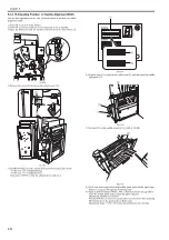
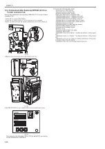
4) Remove the screw [2] to remove the switch cover [1].
F-5-158
5) Set DIP SW382 [1] on the switch PCB as shown in the figure below.
F-5-159
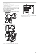
6) Press switch SW385 [1] so that this adjustment is ready now.
F-5-160
7) Pressing push switch SW384 [1] once displays "+1" on the LED [2].
F-5-161
8) Press switch SW385 [1] again to complete this adjustment.
F-5-162
5.3.2.24 Adjustment in the Case of Canceling Limit for
Tray Stack
0021-1732
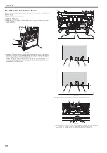
Execute this adjustment in the case of canceling the limit for tray stacking of
coated paper or extra-length paper or replacing EEPROM (IC107) on the fin-
isher controller PCB.
[1]
[2]
[1]
SW382
SW381
SW383
(-)
(+)
ENTER
SW384 SW385
DSP381
[1]
SW382
SW381
SW383
(-)
(+)
ENTER
SW384 SW385
DSP381
[1]
SW382
SW381
SW383
(-)
(+)
ENTER
SW384 SW385
DSP381
[1]
[2]
SW382
SW381
SW383
(-)
(+)
ENTER
SW384 SW385
DSP381
[1]
Summary of Contents for Saddle Finisher-AF2
Page 1: ...SERVICE MANUAL Saddle Finisher AF2 MARCH 6 2009...
Page 2: ......
Page 6: ......
Page 12: ...Contents...
Page 13: ...Chapter 1 Specifications...
Page 14: ......
Page 16: ......
Page 22: ......
Page 23: ...Chapter 2 Installation...
Page 24: ......
Page 26: ......
Page 55: ...Chapter 3 Functions...
Page 56: ......
Page 58: ......
Page 104: ...Chapter 3 3 46...
Page 105: ...Chapter 4 Parts Replacement Procedure...
Page 106: ......
Page 110: ......
Page 157: ...Chapter 4 4 47 F 4 213 3 2 1...
Page 158: ......
Page 159: ...Chapter 5 Maintenance...
Page 160: ......
Page 209: ...Chapter 5 5 47 F 5 221 SW382 SW381 SW383 ENTER SW384 SW385 DSP381 1...
Page 218: ......
Page 219: ...Appendix...
Page 220: ......
Page 221: ...General Timing Chart General Circuit Diagram Finisher Sorter DeliveryTray Saddle Finisher AF2...
Page 222: ......
Page 224: ......
Page 225: ...Contents 1 General Circuit Diagram 1 Signal Names 1 General Circuit Diagram 9...
Page 226: ......
Page 243: ......
Page 244: ......


